Cordless drill EN
11
10
11
10
switch trigger, place the direction of rotation
selector in the center position.
4. REVERSIBLE (SEE FIG.B)
For drilling and screw driving use forward
rotation marked “
” (lever is moved to the
left). Only use reverse rotation marked “
”
(lever is moved to the right) to remove screws
or release a jammed drill bit.
Warning: Never change the direction
of rotation when the chuck is
rotating, wait until it has stopped!
5. TWO-SPEED GEAR TRAIN (SEE FIG.C)
The drill has a two-speed gear train designed
for drilling or driving at LO (mark is 1) or HI
(mark is 2) speeds. A slide switch is located on
top of the drill to select either LO or HI speed.
When using the drill in the LO speed range,
the speed will decrease and the drill will have
greater power and torque. When using the
drill in the HI speed range, the speed will
increase and the drill will have less power and
torque.
Warning: To prevent gear damage,
always allow the chuck to come
to a complete stop before changing the
direction of rotation or the two-speed
gear train.
6. CHUCK ADJUSTMENT
To open the chuck jaws rotate the front section
of the chuck. Insert the drill bit between the
chuck jaws and rotate the front section in the
opposite direction. Ensure the drill bit is in
the center of the chuck jaws. Finally, firmly
rotate the front chuck section in the opposite
directions. Your drill bit is now clamped in the
chuck.
7. TORQUE ADJUSTMENT AND HAMMER
OR DRILLING CONTROL (SEE FIG.D.1&
D.2)
(Screw driving force of your drill driver)
The torque is adjusted by rotating the torque
adjustment ring. The torque is greater when
the torque adjustment ring is set on a higher
setting. The torque is less when the torque
adjustment ring is set on a lower setting.
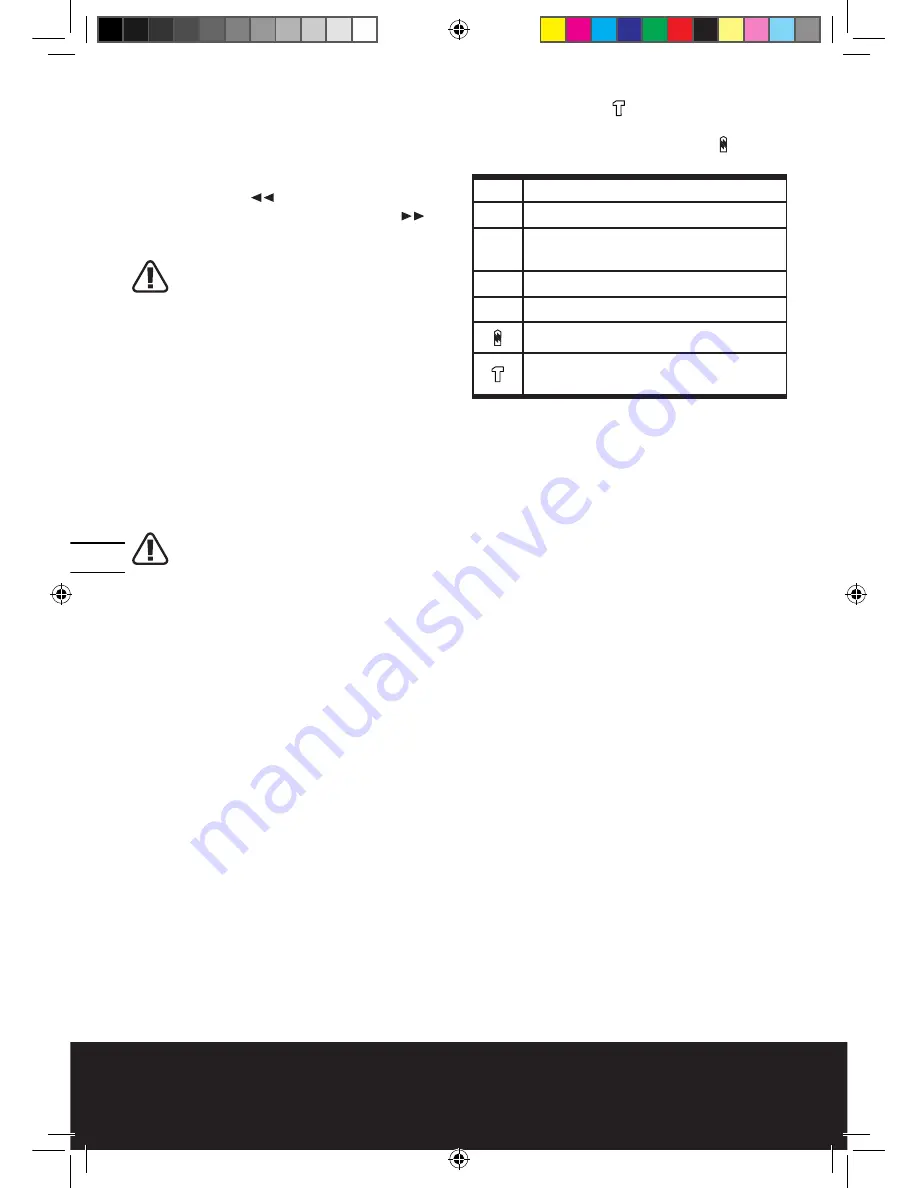
When drilling in masonry and concrete choose
the hammer position . (for WU364/366/376)
When drilling in wood, metal, plastic and
screwdriver choose the drill position .
Make the setting as follows:
1 - 4 for driving small screws
5 - 9 for driving screws into soft material
10 - 14 for driving screws into soft and hard
material
15 - 19 for driving screws into hard wood
20 - 23 for driving larger screws
for heavy drilling
for drilling in masonry and concrete
(for WU364/366/376)
8. AUTOMATIC SPINDLE LOCK
(SEE FIG.E)
The automatic spindle lock allows you to
use as a regular screwdriver. You can give an
extra twist to firmly tighten a screw, loosen
a very tight screw or continue working
when the battery energy has expired. For
manual screwdriver purposes, the chuck is
automatically locked when the tool is off.
9. BIT STORAGE (SEE FIG.F)
The bits provided with the drill can be placed
in the storage area located at the side of the
drill, slide in and out.
10. LEVEL DRILLING (SEE FIG.G)
The bubble level is recessed in the motor
housing of your drill-driver on top. It can be
used to keep drill bits level during horizontal
drilling operation.
11. DRILLING
When drilling into a hard smooth surface,
use a center punch to mark the desired hole
location. This will prevent the drill bit from
slipping off center as the hole is started. Hold
the tool firmly and place the tip of the bit at
the point to be drilled. Depress the switch
trigger to start the tool. Move the drill bit into
the workpiece, applying only enough pressure
to keep the bit cutting. Do not force or apply
side pressure to elongate a hole.
13L-WU150 WU155 WU162 WU364 WU366 WU376-070305.indd 10
3/30/2007 2:04:47 PM
Summary of Contents for WU150
Page 2: ...13L WU150 WU155 WU162 WU364 WU366 WU376 070305 indd 2 3 30 2007 2 04 13 PM ...
Page 3: ...13L WU150 WU155 WU162 WU364 WU366 WU376 070305 indd 3 3 30 2007 2 04 13 PM ...
Page 101: ...101 13L WU150 WU155 WU162 WU364 WU366 WU376 070305 indd 101 3 30 2007 2 05 52 PM ...
Page 102: ...13L WU150 WU155 WU162 WU364 WU366 WU376 070305 indd 102 3 30 2007 2 05 52 PM ...
Page 103: ...13L WU150 WU155 WU162 WU364 WU366 WU376 070305 indd 103 3 30 2007 2 05 52 PM ...
Page 104: ...13L WU150 WU155 WU162 WU364 WU366 WU376 070305 indd 104 3 30 2007 2 05 52 PM ...


