Rev 1.0/2-17
3
#35204
5) If either of the tilt lock plate slots do not align with the tilt linkage, the width of the tilt lock
plate assembly may be adjusted, as follows:
Loosen the four 1/4-20 x 3/4" socket-head screws (#10), to allow the individual sections of
the lock plate assembly to slide with respect to each other.
Adjust the width of the tilt lock plate assembly as needed to install all four mounting
screws/washers, as described in step 4.
Then tighten the 1/4-20 x 3/4" socket-head screws (#10) securely in the tilt lock plate
assembly.
6) Stretch the springs (#5) slightly and slip their mounting rings over the 1/4" dia. x 5/16"
shoulder screws (#2) installed in step 3.
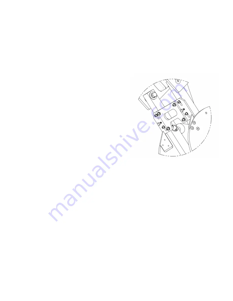
7) Apply grease to the tilt lock ramp plates (#3 &
#11) where they contact the tilt lock catch
plates (#7). Then tilt the pad frame to the
horizontal and vertical positions, to ensure that
the catch plates slide freely on the ramp plates
and securely engage behind them, as shown.
If the catch plates do not fit securely behind the
ramp plates, adjust the tilt stop cams (#1 &
#12), as follows:
Loosen the retaining screw and rotate a cam as
needed to increase or decrease the distance the
pad frame can move before coming to a stop.
Note that two cams limit vertical movement and
two cams limit horizontal movement. Make sure
both vertical cams contact the tilt linkage bars
simultaneously, and likewise for both horizontal cams.


