MRTALP8-DC3: #35059
Rev 8.0/1-20
28
T
O
R
ELEASE
THE
P
ADS
FROM
THE
L
OAD
1A
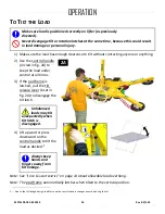
Make sure load is at rest and fully supported before
releasing vacuum pads.
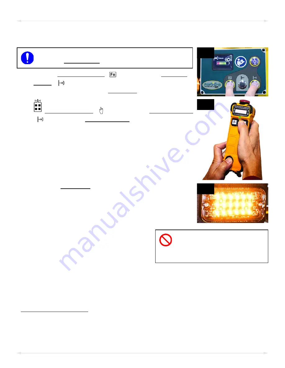
1) Hold the “function” button (
, fig. 1A) and the “release”
button (
, fig. 1A). If the vacuum seal does not break,
follow the directions on the LCD screen.
1B
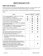
To use the optional Remote Control System, hold the
“function” button (
, fig. 1B) and the “release” button
(
, fig. 1B) on the
radio transmitter.
1C
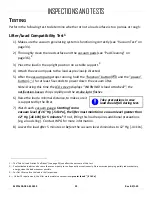
Note: The strobe light (fig. 1C) flashes while the “function” or
“release” button is held, to show the operator that signals
are being transmitted and to warn others that the operator
may be releasing the load.
2)
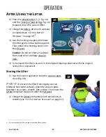
Do not move lifter until pads
release completely, because
such movement could result in load
damage or personal injury.
Continue to hold the “function” and
“release” buttons until the vacuum pads
release the load completely. Otherwise, the
vacuum lifter will automatically revert to
“attach” mode.
1
After the load is successfully released, the lifter activates the “Power Save” mode
automatically.
3) Before you lift another load, perform the Every-Lift Inspection (see “I
on page 31).
1..... A “Timed Release” function can be used to help separate the lifter from the load: Hold the “function” and “release” buttons until a yellow arrow
appears on the LCD screen. Then tap the “function” button 2 or more times. This prolongs the release mode for 5 seconds per each additional
tap.
OPERATION
Summary of Contents for MRTALP810CDC3O
Page 2: ...MRTALP8 DC3 35059 Rev 8 0 1 20 2 ...
Page 6: ...MRTALP8 DC3 35059 Rev 8 0 1 20 4 Note A standard MRTALP811LDC3 is shown SPECIFICATIONS ...
Page 11: ...Rev 8 0 1 20 MRTALP8 DC3 35059 9 TO CHANGE THE PAD FRAME CONFIGURATION ASSEMBLY ...
Page 47: ...Rev 8 0 1 20 MRTALP8 DC3 35059 45 ...
Page 48: ...MRTALP8 DC3 35059 Rev 8 0 1 20 46 ...
Page 49: ......
Page 50: ......

