Rev 10.3/10-16
15
MTCL8FS10TDC: #35079
CAUTION: Examine each air filter regularly, and empty when necessary.
Two air filters help protect the vacuum generating system from contaminants. However, the
lifter is not intended for use on wet load surfaces because the filters would not necessarily
prevent liquid from entering the vacuum system. In order for a filter to function, the operator
must empty the filter bowl before enough liquid accumulates to contact any portion of the filter
element (see MAINTENANCE: A
IR
F
ILTER
M
AINTENANCE
).
Confirming the Pad Frame Configuration
WARNING: Load Capacity of lifter varies, depending on pad frame configuration.
Make sure the pad frame has been assembled in the configuration that will provide optimal
support of the load while lifting (see ASSEMBLY: T
O
C
HANGE THE
P
AD
F
RAME
C
ONFIGURATION
). The
pad frame configuration selected must be appropriate both for the weight and for the dimensions
of the load to be lifted.
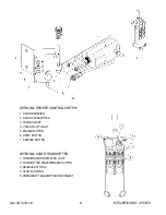
Preparing to Use the Optional Remote Control System
If the lifter is equipped with a Remote Control System, the operator can engage the lifter's apply
and release functions at distances up to 250 ft [76 m], provided there is a direct and clear view
of the lifter and its status indicators from the operator location (see MAINTENANCE: R
EMOTE
C
ONTROL
S
YSTEM
T
EST
). When lifting a load from a remote location, the operator must monitor the
lifter at all times to make sure that it is functioning as intended.
In addition, the operator must
exercise special care to ensure that the load is landed and supported correctly before releasing
the load (see T
O
R
ELEASE THE
P
ADS FROM THE
L
OAD
to follow).
The radio transmitter is also equipped with an emergency transmitter disconnect that prevents
the transmitter from sending any transmission. This button should not need to be used, but may
have to be reset if accidentally engaged. To reset, twist the button clockwise while allowing it to
spring outward to its normal position.
T
O
A
PPLY THE
P
ADS TO A
L
OAD
Powering up the Lifter
Place the lifter's power switch in the “on” ( ) position.
The blue power light remains
illuminated while the lifter is powered up. Keep the power switch in the “on” position while lifting
a load. Any power interruption during a lift could result in the release of a load and possible
injury to the operator or others (see T
O
L
IFT AND
M
OVE THE
L
OAD
: In Case of Power Failure to
follow).
WARNING: Never turn power off while lifting.
4
The Remote Control System is designed with safeguards to prevent multiple lifters from responding until a clear transmission is
received. Nevertheless, radio controlled lifters should be tested to ensure that each transmitter controls only one lifter. The
buttons located on the lifter function regardless of any radio transmissions in the vicinity.
5
When the operator powers up the lifter, either the stand-by function or the apply function is automatically activated, depending
on which was used last. If a vacuum pump or any other powered component fails to function while the lifter's power switch is in
the “on” position, examine each circuit breaker (adjacent to power switch) to determine whether it has interrupted the electrical
circuit to the component. Although the operator can reset the circuit breaker, the power interruption may indicate an electrical
problem that requires attention. Correct any deficiency before resuming normal operation of the lifter (see wiring diagram
provided).
Summary of Contents for MTCL8FS10TDC
Page 2: ...View Quick Start Guide...
Page 40: ...Rev 10 3 10 16 38 MTCL8FS10TDC 35079...
Page 41: ...Rev 10 3 10 16 39 MTCL8FS10TDC 35079...
Page 42: ...Rev 10 3 10 16 40 MTCL8FS10TDC 35079...
Page 43: ...Rev 10 3 10 16 41 MTCL8FS10TDC 35079...
Page 44: ...Rev 10 3 10 16 42 MTCL8FS10TDC 35079...

