Rev 10.3/10-16
8
MTCL8FS10TDC: #35079
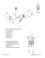
4) To use the movable control pendant (instead of the optional Remote Control System), insert
the plug of its coiled cord into the controls receptacle on the power system enclosure. Then
secure the connector by tightening its threaded collar.
5) Assemble the pad frame in the configuration that will provide optimal support of the load
while lifting (see T
O
C
HANGE THE
P
AD
F
RAME
C
ONFIGURATION
to follow).
6) Open the power system enclosure and connect the electrical connectors uniting the battery to
the battery charger and the vacuum generating system. Now the lifter is operational.
7) Perform Operational and Load Tests for the lifter as directed in MAINTENANCE: T
ESTING
S
CHEDULE
. If the lifter is equipped with a Remote Control System, also perform the R
EMOTE
C
ONTROL
S
YSTEM
T
EST
(see MAINTENANCE).
T
O
C
HANGE THE
P
AD
F
RAME
C
ONFIGURATION
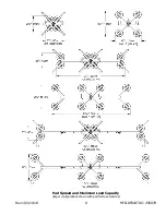
This lifter offers a variety of pad frame configurations to accommodate different load dimensions
and weights (see illustrations on following page). Configurations are created by positioning or
removing the pad mounts, and/or by installing or removing pad frame extensions. Always
arrange the vacuum pads in a symmetrical configuration, in both width and length dimensions.
CAUTION: Vacuum pads must be mounted on main pad frame at all times.
To prevent lifter damage and to provide adequate load support, 4 activated vacuum pads must
be mounted on the main pad frame, regardless of the configuration selected (see illustrations on
following page). It is especially important to observe this rule when pad frame extensions are
employed: The vacuum pads may not be located solely on the extensions, as such a
configuration would not provide adequate load support.
The lifter is equipped with a dual vacuum system, as indicated by color-coded vacuum hoses.
For maximum effectiveness, adjacent vacuum pads must be connected to separate circuits of the
vacuum system in an even distribution. Make sure that an equal number of pads is connected to
the green circuit and to the red circuit.
After changing the pad frame configuration, make sure all vacuum hoses are secure and routed
to avoid being pinched, snagged, abraded or otherwise damaged while the lifter is in operation.
Also be sure to verify that all pads are connected and functioning correctly.
Summary of Contents for MTCL8FS10TDC
Page 2: ...View Quick Start Guide...
Page 40: ...Rev 10 3 10 16 38 MTCL8FS10TDC 35079...
Page 41: ...Rev 10 3 10 16 39 MTCL8FS10TDC 35079...
Page 42: ...Rev 10 3 10 16 40 MTCL8FS10TDC 35079...
Page 43: ...Rev 10 3 10 16 41 MTCL8FS10TDC 35079...
Page 44: ...Rev 10 3 10 16 42 MTCL8FS10TDC 35079...

