background image

Rev 10.3/10-16 

28 

MTCL8FS10TDC: #35079 

V

ACUUM 

P

AD 

M

AINTENANCE


Friction Coefficient 

The friction coefficient represents the lifter's ability to resist load slippage when the load is 

oriented in any position except horizontal.  If the contact surfaces of either the load or the 

vacuum pads are not clean, dry and in good condition, slippage is more likely to occur. 
The Load Capacity of most Powr-Grip lifters is based on a friction coefficient of 1 (only Flat Lifters 

are exempt from this requirement).  However, a vacuum pad's ability to maintain this friction 

coefficient is reduced by factors such as contamination, wear, age and exposure to sunlight, as 

well as the condition of the load's contact surface (see INTENDED USE: L

OAD 

C

HARACTERISTICS

).  

Pads that have surface contamination must be thoroughly cleaned (see Cleaning discussion to 

follow).  Over time, the rubber in a pad may experience hardening or leaching of chemicals, 

resulting in stiffness or surface glaze.  Pads that exhibit wear, stiffness or glaze must be replaced. 
In addition, all pads should be replaced on a regular basis, preferably after no more than 2 years, 

to ensure that the friction coefficient is not compromised.  If necessary, contact your dealer or 

Wood's Powr-Grip for more information. 

Inspection 

Inspect each vacuum pad for the following deficiencies routinely, as directed in the preceding 

I

NSPECTION 

and T

ESTING 

S

CHEDULES

.  Correct any deficiency before using the lifter. 

• Contaminates on the pad face or sealing ring:  Soil build-up can prevent pads from sealing 

adequately or reduce the friction coefficient (see discussion preceding).  Follow the directions 

to clean pads as necessary (see discussion to follow). 

• Filter screen missing from pad face:  This screen helps prevent debris from plugging the 

vacuum hose and the air filter.  Replace any missing screen immediately (see REPLACEMENT 

PARTS LIST). 

WARNING:  Replace any sealing ring that has any nicks, cuts, abrasions or other 

deterioration. 

• Nicks, cuts, abrasions other deterioration in sealing rings:  Pad damage can reduce the lifting 

capacity.  Replace any damaged sealing ring immediately (see discussion to follow). 

Cleaning 

Regularly clean each vacuum pad to remove oil, dust and any other contaminates.  Acceptable 

cleaning agents include soapy water and other mild cleansers.  Do 

not use solvents, petroleum-

based products (including kerosene, gasoline and diesel fuel) or any harsh chemicals for 

cleaning.  Do 

not use unauthorized rubber cleaners or conditioners, such as those intended for 

cleaning tires or vinyl surfaces, because those products can leave a hazardous film on vacuum 

pads which significantly reduces their lifting capacity (see Friction Coefficient preceding).  The 

use of any unauthorized cleaning agent is prohibited because it could damage the pad and/or 

create a hazard to the operator or others. 

WARNING:  Never use solvents, gasoline or other harsh chemicals to clean 

vacuum pad. 

WARNING:  Never use unauthorized rubber cleaners or conditioners to clean 

vacuum pad. 

Summary of Contents for MTCL8FS10TDC

Page 1: ...ee serial label and record number here CLADDING LIFTER DC VOLTAGE WITH DUAL VACUUM SYSTEM AND VPFS10T PADS READ ALL INSTRUCTIONS AND WARNINGS BEFORE OPERATING THIS LIFTER DESIGNED FOR THE MATERIALS HA...

Page 2: ...View Quick Start Guide...

Page 3: ...me Configuration 15 Preparing to Use the Optional Remote Control System 15 TO APPLY THE PADS TO A LOAD 15 Powering up the Lifter 15 Positioning the Lifter on the Load 16 Sealing the Pads against the L...

Page 4: ...Cleaning 28 Sealing Ring Replacement 29 VACUUM TEST 29 Dual Vacuum Circuit Test 30 REMOTE CONTROL SYSTEM TEST 30 TILT DAMPER ADJUSTMENT 31 TILT LATCHES ADJUSTMENT 31 AIR FILTER MAINTENANCE LARGE 32 Fi...

Page 5: ...e inches of Hg and negative kPa Vacuum Lift Lights 2 green lights are energized whenever vacuum level is sufficient for lifting maximum load weight higher than 16 Hg 54 kPa Low Vacuum Warning Buzzer M...

Page 6: ...Always position the vacuum pads correctly on the load prior to lifting see OPERATION TO APPLY THE PADS TO A LOAD Never lift a load when any vacuum indicator shows inadequate vacuum Never touch the va...

Page 7: ...4 POWER SYSTEM ENCLOSURE with 2 LIFT BAR 10 VACUM PAD 18 BATTERY TEST BUTTON VACUUM PUMPS 3 TILT DAMPER 11 PAD MOUNT 19 POWER LIGHT VACUUM SWITCHES 4 TILT CONTROL LEVER 12 CONTROL HANDLE 20 CHARGER CO...

Page 8: ...L RADIO TRANSMITTER 1 RADIO RECEIVER 2 RADIO TRANSMITTER 3 STROBE LIGHT 4 VACUUM LIFT LIGHT 5 ENABLE BUTTON 6 APPLY BUTTON 7 RELEASE BUTTON 1 TRANSMISSION INDICATOR LIGHT 2 TRANSMITTER POWER ENABLE BU...

Page 9: ...lift point when lifted or tilted upright see OPERATION TO TILT THE LOAD the lift point must be adjusted to prevent interference between the adjustable lift point tube and the load Failure to do so ma...

Page 10: ...ning or removing the pad mounts and or by installing or removing pad frame extensions Always arrange the vacuum pads in a symmetrical configuration in both width and length dimensions CAUTION Vacuum p...

Page 11: ...Rev 10 3 10 16 9 MTCL8FS10TDC 35079 Pad Spread and Maximum Load Capacity larger configurations shown with pad frame extensions...

Page 12: ...cotterless hitch pin in the pad mount with the corresponding holes in the pad frame 3 Use the quick connector to connect the vacuum hose from the vacuum pad to the appropriate circuit of the vacuum s...

Page 13: ...pplication cannot be avoided Wood s Powr Grip does offer a heat resistant rubber compound and other solutions which may enable you to lift loads with higher surface temperatures Contact Wood s Powr Gr...

Page 14: ...ct surfaces of the load or vacuum pads diminishes the lifter s slip resistance thereby reducing the lifting capacity see MAINTENANCE VACUUM PAD MAINTENANCE Friction Coefficient WARNING Moisture reduce...

Page 15: ...Rev 10 3 10 16 13 MTCL8FS10TDC 35079 TYPICAL APPLICATIONS Though the lifter is designed with the flexibility to be used in many different ways these illustrations represent some typical applications...

Page 16: ...ery energy before using lifter See MAINTENANCE BATTERY TEST Perform all inspections and tests required by the INSPECTION and TESTING SCHEDULES see MAINTENANCE In addition if the lifter has been in sto...

Page 17: ...ROM THE LOAD to follow The radio transmitter is also equipped with an emergency transmitter disconnect that prevents the transmitter from sending any transmission This button should not need to be use...

Page 18: ...er is positioned above center tilt latches must be locked out before lifting load If the lifter is positioned above center on a load encountered in the flat orientation the load automatically tilts to...

Page 19: ...be drawn immediately at the vacuum pads The low vacuum warning buzzer also sounds an alarm until the lifter attains sufficient vacuum to lift the maximum load weight see TO LIFT AND MOVE THE LOAD Loa...

Page 20: ...the load If the load has rough or porous surfaces the operator must conduct a test to determine whether the lifter is designed to lift the load as follows 1 Make sure the lifter s vacuum generating s...

Page 21: ...ft WARNING Vacuum indicators must be visible to operator throughout entire lift If the vacuum system experiences leakage while the lifter is attached to the load the vacuum pumps turn on and off autom...

Page 22: ...ower failure Although the lifter is designed to support the load for at least 5 minutes without power this depends on many factors including the condition of the load and the lifter s vacuum system se...

Page 23: ...as the load begins to tilt Lift upward or press downward on the control handles to tilt the load as desired and continue to apply pressure as necessary to maintain the desired load orientation If load...

Page 24: ...e transmitter or on the lifter to force air into the vacuum pads quickly breaking the vacuum seal Continue to hold both buttons until the vacuum pads disengage completely from the load If the lifter i...

Page 25: ...32 to 70 Fahrenheit 0 to 21 Celsius Higher temperatures require the battery to be charged more frequently Storage at temperatures above 100 Fahrenheit 38 Celsius should be avoided TO REPLACE SEALING...

Page 26: ...fter is out of service for 1 month or more Examine the lifter s structure for visual damage Examine the vacuum system including vacuum pads fittings and hoses for visual damage Examine the air filters...

Page 27: ...lation 11 Employ the following method to test with an actual load 1 Place a test load with appropriate LOAD CHARACTERISTICS see INTENDED USE on a stable support Make sure the load is oriented in the u...

Page 28: ...is when only red lights are illuminated regardless of the estimated energy requirement WARNING Never use lifter if battery energy is lower than 50 of capacity While the lifter s power switch is in th...

Page 29: ...r switches to a maintenance mode and charging level light 4 green turns on The blue light on the battery gauge also turns on to indicate that the battery is fully charged Be sure to unplug the charger...

Page 30: ...orrect any deficiency before using the lifter Contaminates on the pad face or sealing ring Soil build up can prevent pads from sealing adequately or reduce the friction coefficient see discussion prec...

Page 31: ...groove 3 Make sure that the sealing ring is secure and fully inserted into the mounting groove around the entire perimeter of the vacuum pad Note If the sealing ring ever comes partially or entirely o...

Page 32: ...he environment where the lifter is normally employed Use the radio transmitter to activate each of the remote functions 18 Vary the location and distance of the transmitter in relation to the lifter t...

Page 33: ...OAD Operating the Tilt Latches the tilt latch mechanism requires adjustment as follows When the tilt latches are engaged the cable should remain taut but should not retract the latch pins at all To ch...

Page 34: ...d bowl seal 5 with mild soap and water and skip to step 7 3 Unscrew the baffle 4 and remove the element and deflector 2 4 Discard the element and the bowl seal 5 5 Clean all internal parts and the bow...

Page 35: ...in the illustration Replacing the Gasket Flap Valves 1 Remove the four head screws 1 and lock washers 2 and remove the head assembly 3 7 2 Invert the head and remove the two valve plate screws 7 Remov...

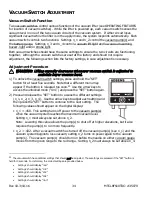
Page 36: ...te that a different menu may appear if the button is released too soon 20 Use the arrow keys to access the unlocked mode UnL and press the SET button again 2 Press and release the SET button to access...

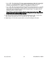
Page 37: ...ng n_4 turns on the low vacuum warning buzzer light and or strobe light and turns off the vacuum lift light This signals a loss of adequate vacuum to the lifter operator Note Setting n_4 corresponds w...

Page 38: ...onet for vacuum lift lights 2 64271 Strobe Light 12 V DC Amber option 1 64262 Green Lens for vacuum lift light on power system enclosure 1 64238AA Vacuum Switch 1 8 NPT Digital w Dual Set Point 2 6421...

Page 39: ...use Repairs are required due to abnormal wear and tear The product has been damaged misused or neglected If a problem is not covered under warranty Powr Grip will notify the customer of costs prior t...

Page 40: ...Rev 10 3 10 16 38 MTCL8FS10TDC 35079...

Page 41: ...Rev 10 3 10 16 39 MTCL8FS10TDC 35079...

Page 42: ...Rev 10 3 10 16 40 MTCL8FS10TDC 35079...

Page 43: ...Rev 10 3 10 16 41 MTCL8FS10TDC 35079...

Page 44: ...Rev 10 3 10 16 42 MTCL8FS10TDC 35079...

Page 45: ...Rev 10 3 10 16 43 MTCL8FS10TDC 35079...

Page 46: ...Rev 10 3 10 16 44 MTCL8FS10TDC 35079...

Reviews: