A310 Accupulser™ Pulse Generator
World Precision instruments
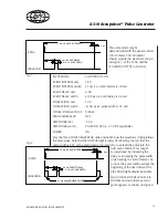
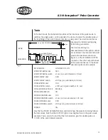
the pulse mode may be
demonstrated with the panel controls
set as follows. the instrument
should provide the waveform shown
on Figure , at the sYnc and the
isolAtor outPut connectors.
inPut mode
continuous on
eVent interVAl dial
.80
eVent interVAl switch x ms (i.e. event interval is .8 ms)
eVent delAY dial
.00
eVent delAY switch
x00 µs (i.e. event delay is 0. ms)
Pulse WidtH dial
.00
Pulse WidtH switch
x00 µs (i.e. pulse width is 0. ms)
sinGle/douBle Pulse sinGle
trAin GenerAtor
oFF
AmPlitude dial
5.00
AmPlitude switch
Pulsed x0V (i.e. ± 5V dc amplitude)
PoWer
on
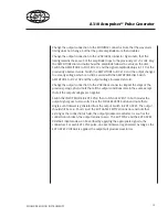
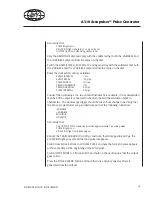
Vary the three Pulse GenerAtor dials and notice how the waveform timing follows
the dial values. note that the outPut light is dimly lit, reflecting the fact that the
pulse width is /8 of the event interval duration. try to extend the pulse into the
next event interval. this may be
accomplished by increasing the
delay or increasing the pulse width
or decreasing the event interval. As
soon as the pulse width overlaps the
beginning of the next interval, the
ViolAtion light should illuminate.
switch sinGle/douBle Pulse to
douBle and note that a second
pulse appears as shown on Figure .
Fig. 1
Fig. 2
5 µs
1.8 ms EVENT INTERVAL
0.4 ms EVENT DELAY
0.1 ms PULSE WIDTH
ISOLATOR
SYNC
1.8 ms EVENT INTERVAL
5 µs
0.4 ms EVENT DELAY
0.1 ms PULSE WIDTH
ISOLATOR
SYNC
0.1 ms wide DOUBLE PULSE
Summary of Contents for A310 Accupulser
Page 21: ......


