background image

A310 Accupulser™ Pulse Generator

World Precision instruments

3

Train

in the train mode, the instrument provides all the functions of the pulse mode. in 
addition, the single pulse can be expanded to a train of pulses. the double pulse at 
the beginning of the event interval, remains as one pulse. the violation function is 

expanded to include overlapping 
train timing parameters.

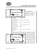
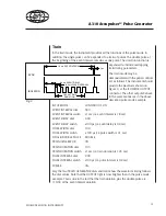
the train mode may be 
demonstrated with the panel controls 
set as follows. the instrument should 
provide the waveform shown on 
Figure 3, at the isolAtor outPut 
connector. the other outputs behave 
in the same manner as in the above 
described pulse mode example.

inPut mode         

continuous on 

eVent interVAl dial    

.80 

eVent interVAl switch    x ms (i.e. event interval is .8 ms) 
eVent delAY dial      

.00 

eVent delAY switch     

x00 µs (i.e. event delay is 0. ms) 

Pulse WidtH dial      

.00 

Pulse WidtH switch    

 x00 µs (i.e. pulse width is 0. ms) 

sinGle/douBle Pulse     douBle 
trAin GenerAtor      

on 

trAin durAtion dial     .05 
trAin durAtion switch    x ms (i.e. train duration is .05 ms) 
Pulse interVAl dial    

.00 

Pulse interVAl switch    x00 µs (i.e. pulse interval is 0. ms) 
PoWer           

on    

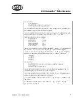
Vary the two trAin GenerAtor dials and notice how the waveform timing follows 
the dial values. note that the outPut light is now brighter than in the pulse mode 
example. this is due to the fact that the train duration plus the double pulse are 
.5/8 of the event interval duration.

Fig. 3

1.8 ms  EVENT INTERVAL

5 µs

0.4 ms EVENT DELAY

ISOLATOR

SYNC

0.2 ms PULSE INTERVAL

1.05 ms TRAIN

DURATION

Summary of Contents for A310 Accupulser

Page 1: ...A310 Accupulser Pulse Generator INSTRUCTION MANUAL Serial No _____________________ 032807 World Precision Instruments www wpiinc com...

Page 2: ...to any language in any form without prior written permission of World Precision Instruments Inc Contents INTRODUCTION 1 SAFETY 2 PREPARATION FOR USE 4 Shipping Information 4 Installation 4 Line Fuse 5...

Page 3: ...st modes The duration of the train burst is easily controlled by using the onboard envelope generator or by externally provided potential or dry contact gating inputs Five separate outputs are availab...

Page 4: ...This instrument is intended to operate from a power source that will not apply more than 250 volts rms between the supply mains conductors or between either supply conductor and ground A protective sa...

Page 5: ...t fuses shall be identical in type voltage rating and current rating Line fuses must match the selected voltage source of AC power and must be changed when the nominal voltage range is changed Do Not...

Page 6: ...absorbing material Installation Input Power CAUTION The A310 Accupulser may be damaged if the Line Voltage Selector switch is not set to match the applied AC power source or the wrong line fuse is in...

Page 7: ...located in the fuseholder on the back panel The fuseholder is opened by inserting a screwdriver in the slot pressing lightly and twisting the cap 1 8 turn counterclockwise Verify that the fuse contai...

Page 8: ...ppropriate signal is applied to either of the two EXT GATES connectors EXT SYNC BNC connector input for an external signal to replace the internal EVENT INTERVAL time base Connector is only active whe...

Page 9: ...to select a twin pulse In the SINGLE PULSE mode the first pulse in an event appears after the elapse of the event delay In the DOUBLE mode in addition of the normal pulse s of the event interval a pul...

Page 10: ...itched outputs synchronous with the other outputs DC outputs with the least amount of noise are obtained by switching the INPUT MODE out of CONTINUOUS ON and not providing an external input VARIABLE A...

Page 11: ...is compatible with WPI Stimulus Isolators MONITOR A BNC connector used to provide output pulses in accordance with the preset timing parameters The signal on the center pin is positive relative to the...

Page 12: ...nd the pulse width are set on the panel controls by the user In the EXT SYNC input mode the internal clock is disabled and the event interval starts whenever an input sync pulse is applied In the SING...

Page 13: ...V DC amplitude POWER ON Vary the three PULSE GENERATOR dials and notice how the waveform timing follows the dial values Note that the OUTPUT light is dimly lit reflecting the fact that the pulse width...

Page 14: ...ltage increases ten fold Change the output connection to the VARIABLE connector Repeat the steps of the previous paragraph and note that all the output conditions remain the same except that all the o...

Page 15: ...US ON EVENT INTERVAL dial 1 80 EVENT INTERVAL switch x1 ms i e event interval is 1 8 ms EVENT DELAY dial 4 00 EVENT DELAY switch x100 s i e event delay is 0 4 ms PULSE WIDTH dial 1 00 PULSE WIDTH swit...

Page 16: ...g of the next interval the VIOLATION light should illuminate Increasing the pulse width to equal the pulse interval will also result in a violation With the above train timing parameters five pulses f...

Page 17: ...asive cleaners Test The Model A310 Accupulser can be tested by following the steps in the Operating Directions section of this manual A different and more specific test is described below To perform a...

Page 18: ...ailable it is recommended that the SYNC output is connected to channel one and the alternate output to channel two The oscilloscope trigger should be taken from channel one Verify that the above set w...

Page 19: ...osure 5 mA max source Outputs SYNC 5 s TTL 5V CMOS compatible 20 mA max sink and source ISOLATOR TTL 5V CMOS compatible 20 mA max sink and source MONITOR 10 15 VDC 50 mA max sink and source VARIABLE V...

Page 20: ...spection requested All claims for shortage or damage must be made within 10 days after receipt of shipment Claims for lost shipments must be made within 30 days of invoice or other notification of shi...

Page 21: ......

Reviews: