(5)
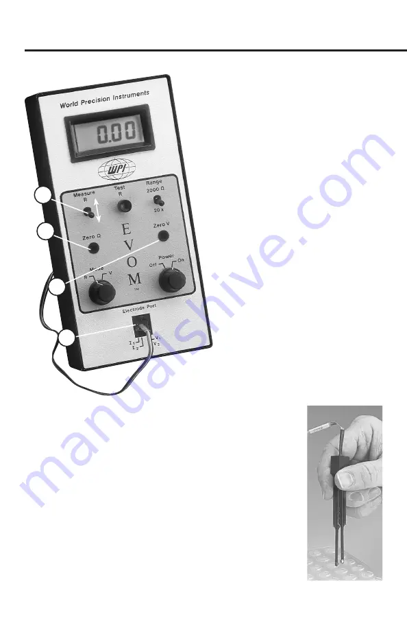
Measure R Toggle Switch (EVOMX):
In
model
EVOMX
, the Measure R pushbutton has
been replaced by a toggle switch and the alarm
deactivated. The toggle switch must be in the
off
position (down) when performing the test
above. In the up position, the switch is
on
for
continuous resistance measurement.
(6)
ZERO
Ω
adjustment screw
: This screw
is used to zero the meter display while in
the R mode. The ZERO
Ω
adjustment affects
the meter display only. It does not offset
residual resistance of the fluid or electrode
(7)
ZERO V adjustment screw:
This
screw is used to adjust the zero in V
mode. It should not be adjusted until the
electrode has been preconditioned.
(8)
Electrode port:
Insertion of the
telephone-type Plug connector of the
STX2
electrode to this port connects
the electrode to the meter.
(9)
Digital LCD Display:
The Digital
LCD Display registers readings up to 4
digits, depending on the scale used. When
the meter is measuring voltage, it displays the potential difference
between the two electrodes in millivolts (mV) up to 199.9 mV.
When the meter is measuring resistance, it displays the resistance
between the two electrode probes in
Ω
(with range switch set to
2000
Ω
) or K
Ω
(with range switch set to 20 K). When a reading is
off scale (high), a single digit “1” will appear at the furthermost left
position, reflecting an off-scale reading.
(10)
STX2 Electrode
: The
STX2
electrode incorporates a fixed
pair of probes, 4 mm wide and 1 mm in thickness. Each probe
has an outer and an inner electrode (see Fig. 1). The outside
electrodes are small silver (Ag) pads that pass current through
the membrane sample. They are referred to as current electrodes
and are connected to the
I
1
and
I
2
pins of the telephone-type
4 WORLD PRECISION INSTRUMENTS
5
EVOMX
6
8
7
ON
OFF


