


Battery Charger Operating Instructions - SPE
GENERAL INFORMATION AND WARNINGS
NSS machines are delivered with the SPE charger
set to Curve #0 for Crown batteries.
Electronic automatic battery charger with
microprocessor suitable for any battery type.
Fully automatic charging cycle with electronic
setting; protected against overload, short-circuit at
clamps and reversed polarity.
Before starting to charge, make sure the voltage of
the equipment suits the voltage of the battery, that
the charging current suits the capacity of the
battery and that the selected charging curve (for
lead-acid batteries or airtight gel batteries) is
correct for the type of battery to be charged. In
addition, make sure the rated input voltage of the
charger suits the available supply voltage and the
system is equipped with grounding.
Pay attention to any remarks of the battery
manufacturer.
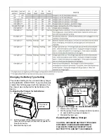
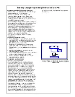
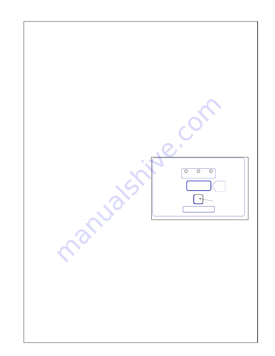
CONTROLS (see figure below)
1. Three-digit d symbol (1), to view
A
= the
charging current,
U
= the battery voltage,
h
= the
charging time,
C
= the charging ampere-hours
[Ah],
E
= the energy used [KWh].
2. Button for the
S
election of the display mode
(2):
A, U, h, C, E
. After about 10 seconds the
display returns to the visualization of the charging
current.
3. Red control indicator (3): when it is on, the
charging cycle has started.
4. Yellow control indicator (4): when it is on, the final
phase of the charging cycle has started.
5.
Green control indicator (5): when it is on, the
charging cycle has finished.
OPERATION INSTRUCTIONS
Plug the cord into a socket.
Now, the battery charger’s display will show a
sequence of details on the charger’s internal
programming: after the name “SPE”, it will show
the software release installed in the equipment,
then, in sequence, the following parameters:
battery voltage, charging current, charging curve
number and, finally, the words
“GEL”
or “
Acd
”
depending on the set up charging curve being
suitable for airtight gel batteries or lead-acid
batteries. Now, a test is run on the battery voltage
to decide if the charging process should be started
or not. If the battery is not connected to the battery
charger, the display will show the word
“bat”
. The
word will stay on, even if the test is failed (for
instance, reversed polarities or incorrect battery
connection). If the test is passed, the display will
show the battery voltage for approximately 5
seconds and the battery will begin to be charged.
The charging cycle progress will be shown by red
(3), yellow (4) and green (5) LED indicators. At the
end of the charge, when the green indicator (5) is
on, unplug the cord from the socket and operate
the machine.
SMART BATTERY CHARGER
MOD. CBHF1-SM 24V 12A
S
A = Amps
U = Volts
h = hours
C = Ah
E = KWh
1
2
3
4
5
F
RONT
P
ANEL OF
B
ATTERY
C
HARGER MODEL
CBHF1-SM
Summary of Contents for 2016 AB
Page 14: ...EC DECLARATION OF CONFORMITY...
Page 15: ...NOTES...