


NOISE AND VIBRATION
MACHINE INSPECTION
Now that the machine is unpacked remember to
recycle all packing materials.
Inspect the machine for damage or missing
components. If damage is found, contact the local
freight company to file a freight claim.
MACHINE COMPONENTS
Solution Tank
The solution tank is the lower part of the machine body
and has a capacity of
16 gal (60.5 L)
.
The amount of water in the tank is measured in the
plastic tube at the right rear of the tank. The solution
tank is emptied through the clear plastic tube at the
right rear of the tank.
Recovery Tank
The recovery tank is the upper part of the machine body
and has a capacity of
17 gal (64.3 L)
.
A round clearview lid assembly closes off the
recovery tank’s opening.
The recovery tank has a foam sensitive float shut-off
assembly. As the water level rises, the float ball will
rise into the tube and shut of the airflow of the
vacuum. NOTE: The float shut-off assembly does
not
shut off the vacuum motor.
Operator Control Panel
The operator control panel is located at the upper rear
area of the machine. This panel has components that
control various machine functions.
The toggle switch on the left controls the brush motor.
The toggle switch on the right controls the vacuum
motor.
The red button is the master power switch; it controls
the power to all components. Power on, is indicated
by the Battery Meter.
Battery Meter
The battery meter is located on the left side of the
operator control panel and shows the state of charge of
batteries during operation.
The battery meter is equipped with a relay that will
open, turning off the machine, when the battery voltage
has dropped to its lowest permissible level.
When the batteries are fully charged, all of the LED’s
are illuminated.
As the batteries discharge, the LED’s start to turn off,
one at a time, from right to left.
When the last yellow LED on the left starts blinking,
there is only a few minutes of runtime left before the
machine is automatically turned off. NOW is the time
to turn off the brushes and vacuum motor, and drive
to the battery charging area.
If the machine is operated until it is automatically shut
off, turn off the master switch, the brush switch, and
the vac switch. Then turn on the master switch, and
the machine can be driven to a charging location
(wheel drive models only).
Circuit Breaker
The circuit breakers are located to the left of the
handle grips.
The right circuit breaker is for the vacuum motor.
The left circuit breaker is for the brush motor.
Wheel Drive models:
The center circuit breaker is for the drive motor.
In the middle of the panel are two (2) rubber twist
grips. These grips rotate forward and backward to
control the direction and speed of the machine. The
farther the grips are rotated, the faster the machine
will move. These twist grips have a feature that
returns the machine to the neutral position when the
handles are released.
Solution Control (Valve) Lever
The solution control lever is located on the left rear
side of the machine. This lever controls the solution
valve and the amounts of liquid put on the floor when
cleaning.
Pull up
on the handle to
open
the valve.
Push down
on the handle to
close
the valve. The
control lever can be placed in notches to maintain
desired flow between the open and closed position.
Solution Filter Assembly
Attached to the solution control valve is a canister
strainer designed to stop debris from entering the
solution solenoid valve.
If the solution stops flowing to the brush, close the
solution control valve and unscrew the canister bowl
(by hand), remove and clean the screen.
Battery Compartment Drain Hose
This hose is tucked up under the lower right side of the
control panel. The spilled liquids from the battery
compartment collect in it. A pinch clamp is used to hold
it closed.
Inspect the hose for liquid level on a weekly basis.
Dispose of liquids according to your local and federal
regulations.
Brush Gear Motor
This machine has a 24-volt brush motor located at the
front of the machine. The motor is attached to a
gearbox to turn the pad driver or brush.
The right lift arm is used to raise or lower the brush
motor to and from transport, float, or heavy scrub
positions.
This motor has carbon brushes that must be serviced
on a regular basis. The carbon brushes have an
expected life of 2,000 operating hours. Refer to the
maintenance section later in this book.
Vacuum Motor
This machine has a 24-volt vacuum motor.
NOISE
Sound pressure level at Operator
position
72
dB(A)
VIBRATION
Weighted RMS acceleration value
(ISO 5349)
.575 m/s
2
Summary of Contents for 2016 AB
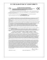
Page 14: ...EC DECLARATION OF CONFORMITY...
Page 15: ...NOTES...