ENGINE
L4100, WSM
1-S33
(EU)
Camshaft and Balancer Shaft
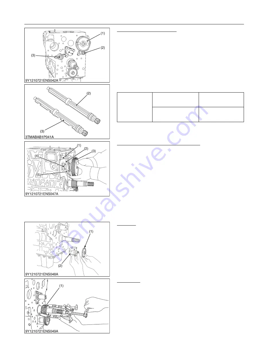
1. Remove the camshaft set screws and draw out the camshaft
(1).
2. Remove the balancer shaft 1 (2) set bolts and draw out the
balancer shaft 1 (2).
3. Remove the balancer shaft 2 (3) set bolts and draw out the
balancer shaft 2 (3).
(When reassembling)
• When install the balancer shaft 1 (2) and 2 (3), be sure to place
the 1st and 4th cylinders piston at the top dead center in
compression then, align all mating marks on each gear to
assemble the timing gears, set the idle gear last.
9Y1210278ENS0102US0
Fuel Camshaft and Fork Lever Assembly
1. Remove the external snap ring.
2. Detach the hydraulic pump drive gear.
3. Remove the fuel camshaft stopper.
4. Remove the three fork lever holder mounting screws.
5. Draw out the fuel camshaft assembly (3), (4) and fork lever
assembly (1), (2), (5) at the same time.
(When reassembling)
• After installation, check to see that the fork lever 1 (1) and 2 (2)
are fixed to the fork lever shaft, and that they can turn smoothly
in the holder (5).
9Y1210278ENS0047US0
Oil Pump
1. Remove the oil pump drive gear mounting nut, and draw out the
oil pump drive gear (1) with a puller.
2. Remove the four oil pump mounting screws.
3. Detach the oil pump (2).
9Y1210278ENS0048US0
Crank Gear
1. Loosen the oil pump drive gear mounting nut.
2. Draw out the crank gear (1) with a puller.
3. Remove the feather key on the crankshaft.
(When reassembling)
• Check to see that the feather key on the crankshaft. Heat the
crank gear to approx. 80 °C (176 °F), and fit on the crankshaft
9Y1210278ENS0049US0
Tightening torque
Camshaft set screw
24 to 27 N·m
2.4 to 2.8 kgf·m
18 to 20 lbf·ft
Balancer shaft set bolt
24 to 27 N·m
2.4 to 2.8 kgf·m
18 to 20 lbf·ft
(1) Camshaft
(2) Balancer Shaft 1
(3) Balancer Shaft 2
(1) Fork Lever 1
(2) Fork Lever 2
(3) Injection Pump Gear
(4) Fuel Camshaft
(5) Fork Lever Holder
(1) Oil Pump Drive Gear
(2) Oil Pump
(1) Crank Gear
KiSC issued 08, 2012 A
Summary of Contents for Kubota L4100
Page 1: ...L4100 WORKSHOP MANUAL TRACTOR KiSC issued 08 2012 A...
Page 3: ...I INFORMATION KiSC issued 08 2012 A...
Page 9: ...INFORMATION L4100 WSM I 5 EU 9Y1210278INI0002US0 KiSC issued 08 2012 A...
Page 13: ...INFORMATION L4100 WSM I 9 EU Mid mount type ROPS 9Y1210278INI0006US0 KiSC issued 08 2012 A...
Page 14: ...G GENERAL KiSC issued 08 2012 A...
Page 67: ...1 ENGINE KiSC issued 08 2012 A...
Page 130: ...2 CLUTCH KiSC issued 08 2012 A...
Page 160: ...3 TRANSMISSION KiSC issued 08 2012 A...
Page 161: ...CONTENTS 1 STRUCTURE 3 M1 MECHANISM KiSC issued 08 2012 A...
Page 201: ...4 REAR AXLE KiSC issued 08 2012 A...
Page 202: ...CONTENTS 1 STRUCTURE 4 M1 MECHANISM KiSC issued 08 2012 A...
Page 210: ...5 BRAKES KiSC issued 08 2012 A...
Page 211: ...CONTENTS 1 STRUCTURE 5 M1 2 OPERATION 5 M2 MECHANISM KiSC issued 08 2012 A...
Page 224: ...6 FRONT AXLE KiSC issued 08 2012 A...
Page 225: ...CONTENTS 1 STRUCTURE 6 M1 2 FRONT WHEEL ALIGNMENT 6 M2 MECHANISM KiSC issued 08 2012 A...
Page 245: ...7 STEERING KiSC issued 08 2012 A...
Page 264: ...8 HYDRAULIC SYSTEM KiSC issued 08 2012 A...


