ELECTRICAL SYSTEM
L4100, WSM
9-S11
(EU)
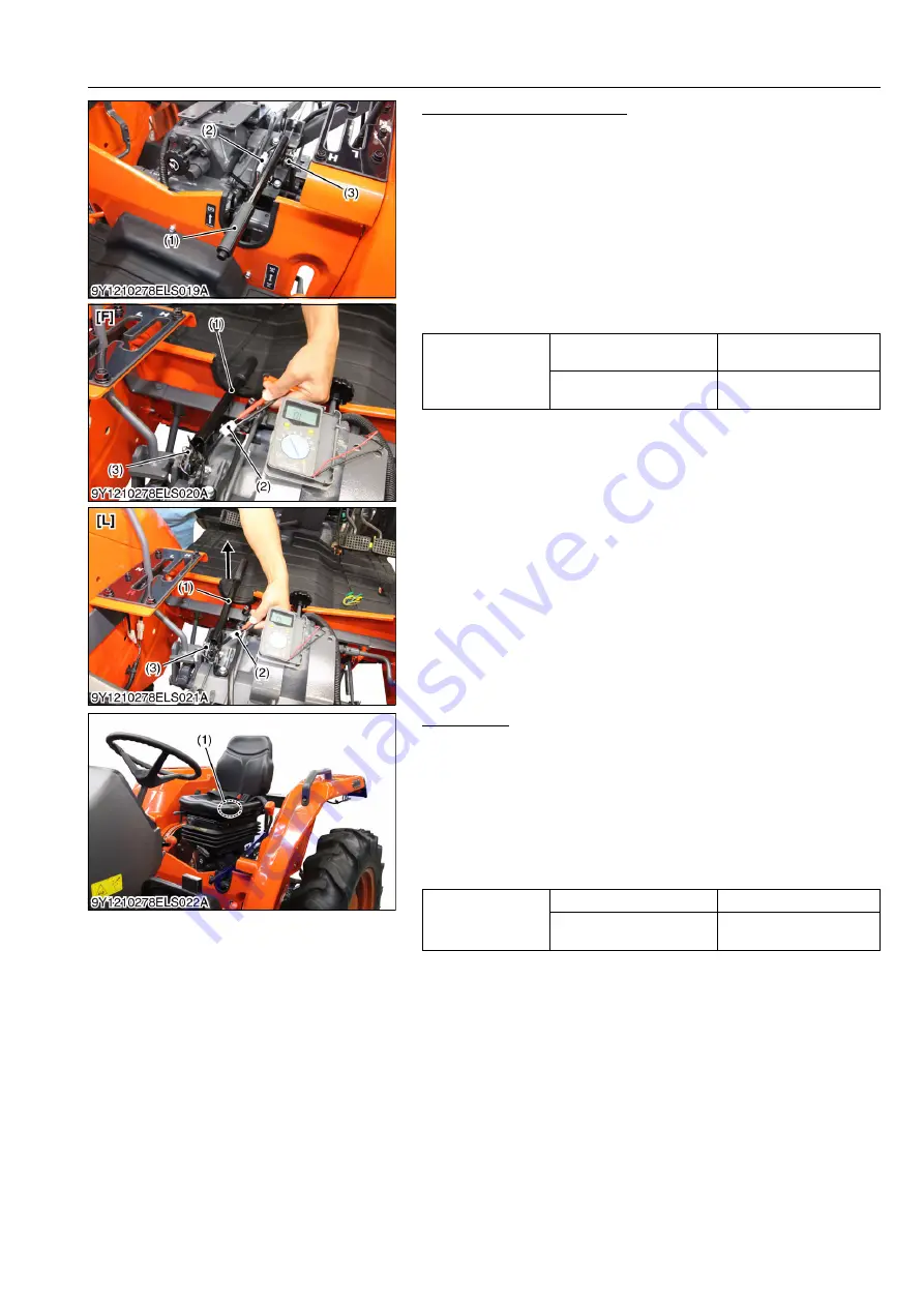
Parking Brake Lever Switch
1. Disconnect the
2P
connector (2).
2. Connect the leads of the circuit tester to the
2P
connector (2).
3. Set the parking brake lever (1) to
"FREE"
and
"LOCK"
position
as shown in the pictures.
4. Measure the resistance.
5. If infinity is not measured when setting the parking brake lever
to
"FREE"
position, the parking brake lever switch (3) is
defective and replace it.
If 0 ohm is not measured when setting the parking brake lever
to
"LOCK"
position, the parking brake lever switch (3) is
defective and replace it.
9Y1210278ELS0032US0
Seat Switch
1. Disconnect the
2P
connector from the seat switch of the
operator's seat.
2. Remove the operator's seat from the tractor body.
3. Connect the leads of the circuit tester to the terminals of the seat
switch.
4. Measure the resistance between the switch terminals.
5. If the safety switch is defective, replace it or replace the
operator's seat with the seat switch.
9Y1210278ELS0033US0
Resistance (Across
switch terminals)
When lever is at
FREE
position
Infinity
When lever is at
LOCK
position
0
Ω
(1) Parking Brake Lever
(2)
2P
Connector
(3) Parking Brake Lever Switch
[F] FREE Position
[L] LOCK Position
Resistance (Across
switch terminals)
When operator sits on seat
0
Ω
When operator stands up
from seat
Infinity
(1) Seat Switch
KiSC issued 08, 2012 A
Summary of Contents for Kubota L4100
Page 1: ...L4100 WORKSHOP MANUAL TRACTOR KiSC issued 08 2012 A...
Page 3: ...I INFORMATION KiSC issued 08 2012 A...
Page 9: ...INFORMATION L4100 WSM I 5 EU 9Y1210278INI0002US0 KiSC issued 08 2012 A...
Page 13: ...INFORMATION L4100 WSM I 9 EU Mid mount type ROPS 9Y1210278INI0006US0 KiSC issued 08 2012 A...
Page 14: ...G GENERAL KiSC issued 08 2012 A...
Page 67: ...1 ENGINE KiSC issued 08 2012 A...
Page 130: ...2 CLUTCH KiSC issued 08 2012 A...
Page 160: ...3 TRANSMISSION KiSC issued 08 2012 A...
Page 161: ...CONTENTS 1 STRUCTURE 3 M1 MECHANISM KiSC issued 08 2012 A...
Page 201: ...4 REAR AXLE KiSC issued 08 2012 A...
Page 202: ...CONTENTS 1 STRUCTURE 4 M1 MECHANISM KiSC issued 08 2012 A...
Page 210: ...5 BRAKES KiSC issued 08 2012 A...
Page 211: ...CONTENTS 1 STRUCTURE 5 M1 2 OPERATION 5 M2 MECHANISM KiSC issued 08 2012 A...
Page 224: ...6 FRONT AXLE KiSC issued 08 2012 A...
Page 225: ...CONTENTS 1 STRUCTURE 6 M1 2 FRONT WHEEL ALIGNMENT 6 M2 MECHANISM KiSC issued 08 2012 A...
Page 245: ...7 STEERING KiSC issued 08 2012 A...
Page 264: ...8 HYDRAULIC SYSTEM KiSC issued 08 2012 A...


