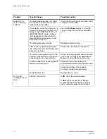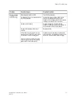
Fault Conditions
PMMK Software F04100
8 - 11
M-032170
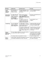
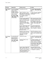
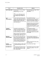
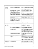
INVERTER OVER
TEMPERATURE:
The chill plate temperature exceeded
+60
o
C, or the thermistor sensor on
the chill plate is open circuit.
NOTE: Do not confuse this fault with
TRANSFORMER OVER TEMPERA-
TURE fault.
Assure proper water flow to the
inverter. Check chill plate tempera-
ture. Remove inverter for service if the
chill plate is NOT hot and the condi-
tion persists.
OUTPUT GROUND:
A current imbalance exists in the
inverter output, indicating that some
current has found a shunt path.
Check weld transformer primary cir-
cuit for shorts to ground,
especially from primary cables with
worn or damaged insulation.
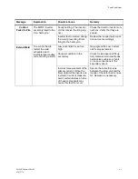
HARD
OVERCURRENT:
The inverter IGBT drive circuit
detected an uncontrolled overcurrent
(desaturation).
~or~
In Primary Voltage Firing mode, the
inverter reached Maximum Primary
Current Limit at the minimum possible
on-time (check 'On-Time' display
value).
Check the weld transformer
primary circuit for shorted or damaged
cables.
Check weld transformer for:
- Internal short circuits,
- Short circuits to ground,
- Defective secondary diodes.
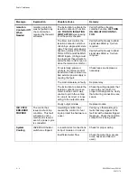
DRIVER LOW
VOLTAGE:
The inverter detected a failure in one
or more IGBT driver circuits.
Replace inverter.
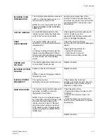
INVERTER SYSTEM
FAILURE:
Failure of inverter CPU board
~
or
~
Failure of inverter charging contactor
(internal) to close.
Replace inverter.
ILLEGAL POWER
FREQUENCY:
The inverter cannot
determine the power line frequency.
Check power line for proper
voltage, all phases present, absence
of excessive noise, spikes, sags or
dropouts on power line.
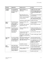
MAIN FUSE OPEN:
The inverter did not detect output volt-
age when an IGBT is turned on
(beginning of weld time).
NOTE: This fault is typically caused
by a disruption of power. Please verify
all power sources supplying the
inverter unit are correct. This fault
may occur when using an external
120V power source. A faulty power
supply will generate a MAIN FUSE
OPEN fault.
Check inverter unit for:
- Proper line voltage on pins 2 and 3
of CNIG4.
- Proper 120V on pins 3 and 4 of
CNIG3.
- Verify that fuses are not blow and
that the control transformer is operat-
ing properly.
Replace inverter.
Summary of Contents for MedWeld 5000
Page 2: ...MedWeld 5000 Technical Reference Manual Modified 1 31 06 M 032170...
Page 6: ...MedWeld 5000 Technical Reference Manual Modified 1 31 06...
Page 38: ...Installing the MedWeld 5000 2 12 MedWeld 5000 Technical Reference Manual M 032170...
Page 82: ...Advanced Software Features 5 12 MedWeld 5000 Technical Reference Manual M 032170...
Page 120: ...Hardware Troubleshooting 9 10 MedWeld 5000 Technical Reference Manual M 032170...


