Setup Parameters
6 - 6
MedWeld 5000 Technical Reference Manual
M-032170
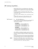
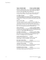
HARD OVERCURRENT:
(FAULT)
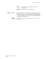
This fault is generated when the inverter detects an uncontrolled current
above the rating of (at least one) IGBT transistor.
DRIVER LOW VOLTAGE:
(FAULT)
This inverter generates this condition on detecting a low voltage
condition on one of the four drivers. The inverter immediately performs
the error shut-down procedure.
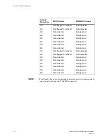
INVERTER SYSTEM FAILURE:
(FAULT)
An INVERTER SYSTEM FAILURE fault is caused by the failure of the
of inverter CPU board or a failure of inverter charging contactor
(internal) to close.
ILLEGAL POWER FREQUENCY: (FAULT)
This failure is generated when the inverter cannot determine the power
line frequency. Check power line for proper voltage, all phases present,
absence of excessive noise, spikes, sags or dropouts on power line.
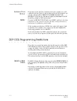
MAIN FUSE OPEN:
(FAULT)
The inverter did not detect output voltage when an IGBT is turned on
(beginning of weld time). Main Fuse (internal to inverter package) is
open: NOT field-replaceable.
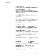
SEC CURRENT SENSOR:
(FAULT)(ALERT)
When operating in the SEC CURRENT firing mode, this fault occurs
when the inverter detects a shorted, malfunctioning or otherwise
defective secondary-current sensor.
INCOMPATIBLE HARDWARE:
(FAULT)
This fault is generated when the inverter detects a hardware error. This
is typically seen when RATED PRIMARY CURRENT is set in the weld
control setup above the range of the inverter installed. For example,
having a 400 A inverter installed in a control and the setup is
programmed for RATED PRIMARY CURRENT (1000 A.) will
generate this fault.
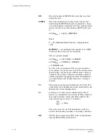
RATED PRIMARY CURRENT:
(150A)(400A)(600A)(1000A)
(2000A)
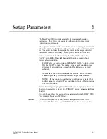
This setting allows the operator to set the rated primary current of the
inverter.
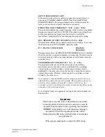
FIRING MODE:
(PRI CURRENT)(PRI
VOLTAGE)
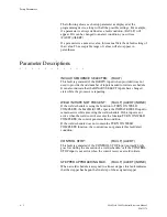
This parameter sets which firing mode to use for the inverter to interpret
the firing signals from the weld processor:
PRI CURRENT
selects the constant current firing mode.
PRI VOLTAGE
selects the constant primary voltage mode.
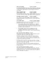
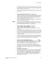
This parameter controls how the inverter will supply weld current. It
also sets how fault conditions will be reported if the desired amount of
energy could not be delivered to the weld.
Summary of Contents for MedWeld 5000
Page 2: ...MedWeld 5000 Technical Reference Manual Modified 1 31 06 M 032170...
Page 6: ...MedWeld 5000 Technical Reference Manual Modified 1 31 06...
Page 38: ...Installing the MedWeld 5000 2 12 MedWeld 5000 Technical Reference Manual M 032170...
Page 82: ...Advanced Software Features 5 12 MedWeld 5000 Technical Reference Manual M 032170...
Page 120: ...Hardware Troubleshooting 9 10 MedWeld 5000 Technical Reference Manual M 032170...

