background image

In User Mode, the Port Diagnostics Screen will display only the status of those ports that share

the same Port Password that was entered at login. Ports that are protected by other passwords

will not be displayed.
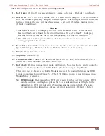
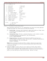
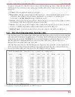
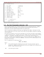
As shown in Figure 6.2, the Port Diagnostics Screen lists the following items:

·

Port:

The Port Number. Note that if this column contains a plus sign (

+

), this indicates

that the port will be allowed to access the Supervisor Mode if the appropriate Supervisor

Password is entered at login.

·

Name:

The user-defined name for each port.

·

Status:

The connect status for each port. When the port is connected, this column will list

the number of the other port that is connected to this port. Note that if this column

contains an asterisk, this indicates that the port has accessed the Command Mode.

·

Baud:

The baud rate selected for each port.

·

COM:

The Data Bits, Parity, and Stop Bits selected for each port. For example, “8N1”

indicates Eight data bits, No parity, and One stop bit.

·

HS:

The handshaking (flow control) mode for each port.

·

Mode:

The user-selected Port Mode. This column will read Any (Any-to-Any), Modem,

Passive, or Buffer, depending on the configuration selected for each port.

·

BUF:

Lists the amount of data (in bytes) currently stored in the buffer for this port.

·

CTS:

The High/Low status of the CTS line at the RS232 interface.

6-3

APS Series - Asynchronous Port Switches, User's Guide

The Status Screens

Summary of Contents for APS-16

Page 1: ...C APS Series Asynchronous Port Switches Firmware Version 2 05 and Higher Models APS 16 APS 8 and APS 4 User s Guide 5 Sterling Irvine California 92618 949 586 9950 Toll Free 1 800 854 7226 Fax 949 583...

Page 2: ...Use only three wire cord which is provided with the unit Abouchent unit qu aux convenable mesura approvisionnement Usage qu trois fil corde laquel est approvisionna avec la unit Anschliesse einheit n...

Page 3: ...certain to provide adequate ventilation for equipment installed at the bottom of the rack 2 Open Racks Make certain that the rack frame does not block the ventilation slots on the instrument cover If...

Page 4: ...se Message Format Sw6 4 3 4 2 4 Default Command Echo Sw7 4 3 4 3 Initialize Unit to Default Settings 4 4 4 4 Connecting Devices to the APS 4 4 4 5 Application Example 4 5 5 Configuration 5 1 5 1 Acces...

Page 5: ...ons Apx 2 C Customer Service Apx 3 Index Index 1 List of Figures 2 1 Instrument Front Panel Model APS 16 Shown 2 1 2 2 Instrument Back Panel Model APS 16 2 2 2 3 Instrument Back Panel Model APS 8 2 2...

Page 6: ...Ports are allowed to change configuration display status and connect to any other port User Ports are only allowed to connect to the ports provided by their password Each individual port can be assign...

Page 7: ...tically Typographic Conventions e g X Indicates a control character For example the text X Control X indicates the Ctrl key and the X key must be pressed simultaneously COURIER FONT Indicates characte...

Page 8: ...d then release the SET button Notes During initialization all port LEDs will flash ON for approximately one half second During initialization all command selected parameters will be cleared and the AP...

Page 9: ...S 16 units SetUp Switches are located on the underside of the unit on APS 8 and APS 4 units the SetUp Switches are located on the instrument back panel 115 230 Voltage Selector AC powered units only P...

Page 10: ...Parity 1 Stop Bit Using Other Parameters for this Overview Optional If desired the APS can match the parameters used by your communications program Refer to Section 4 2 and configure SetUp Switches ac...

Page 11: ...t used by your communications program Connect the other end of the cable to APS Port 1 For a description of the port interface please refer to Appendix A 3 5 Communicating with the APS Unit Perform th...

Page 12: ...o Port 2 type C 2 Enter While Port 1 is connected the APS will not recognize commands issued at Port 1 However the unit will recognize a Resident Disconnect Sequence issued at Port 1 or Port 2 ii Issu...

Page 13: ...ill appear Key in the desired text up to 32 characters and press Enter b To display the Site I D type J Enter c Note that the Site I D will be cleared when the unit is initialized This completes the i...

Page 14: ...C Powered Units The Voltage Selector Switch on the instrument back panel is used to set the unit for 115V or 230V AC power Plug the supplied power cable into the receptacle on the APS back panel and t...

Page 15: ...ng parameters baud rate parity etc can be selected for each port using the P command as described in Section 5 5 The P command can select different parameters for each APS port When the APS is initial...

Page 16: ...on the P command can also set the response format to none Quiet Mode When Quiet Mode is selected the unit will not send response messages Note that the P command can also be used to select a different...

Page 17: ...de 2 Determine which APS port will be used for connection to the new device e g Port 3 3 Check Buffer Type S Enter to display the Port Status Screen Check the Buffer Count column which lists the amoun...

Page 18: ...e allowed to adjust port configuration connect to any port or review unit status Users are only allowed to review status and connect to the ports allowed by their Port Password Ports 5 7 and 9 User Po...

Page 19: ...visor Password a prompt will be displayed Key in your Supervisor or Port password and press Enter If the Supervisor Password has not been defined just press Enter The APS prompt will appear 5 2 System...

Page 20: ...ose your Supervisor Password you will not be able to access Supervisor Level Commands In this case the only way to access the Supervisor Mode is to reinitialize the APS to default values as described...

Page 21: ...are defined via the System Parameters menu F Notes The Site ID cannot include double quotes The Supervisor Password cannot include an asterisk forward slash spaces or double quotes Both the Site ID an...

Page 22: ...y Mode Allows communication between connected ports Any to Any Mode Ports can be connected to other Any to Any Mode Passive Mode Buffer Mode or Modem Mode Ports by accessing Command Mode and invoking...

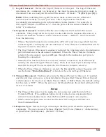
Page 23: ...to configure Port 2 type P 2 Enter The Port Configuration menu will appear Figure 5 1 a If the P Command is entered without the port number e g P Enter the configuration menu for your resident port w...

Page 24: ...r the port Can be set to any standard rate from 300 bps to 115 2K bps Default Selected By SetUp Switches 1 2 and 3 4 Bits Parity Default 8 None 5 Stop Bits Default 1 6 Handshake Mode Selects the hands...

Page 25: ...l not be changed until you exit from command mode and discontinue the modem connection to the unit 8 Supervisor Mode Permits or denies access to Supervisor Mode When enabled Permit and the valid Super...

Page 26: ...ence will pass through to the destination port prior to breaking the connection When the One Character format is selected resident connections are terminated by entering the selected Logoff Character...

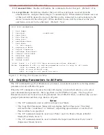
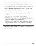
Page 27: ...a select group of parameters and then copy them to all ports Notes The CP command is only available in Supervisor Mode The Copy Port Parameters Menu will not display the Port Password This field will...

Page 28: ...r Menu After defining several parameters if you wish to clear the CP menu and start again type dash and press Enter the menu will be reset 5 Exit Without Copy To exit from the Copy Parameters menu wit...

Page 29: ...Status Screen offers the option to either display or suppress Port Passwords Normally when the S command is invoked the Password column will read either defined or undefined depending upon whether or...

Page 30: ...appear as shown in Figure 6 2 Note that the APS 8 Port Diagnostics Screen will show only eight ports and the APS 4 Port Diagnostics Screen will show only four ports Like the Port Status Screen the Po...

Page 31: ...onnected this column will list the number of the other port that is connected to this port Note that if this column contains an asterisk this indicates that the port has accessed the Command Mode Baud...

Page 32: ...Port Parameters Screen with the Port Password type WP followed by the desired port number and then press Enter Note that the WP command option is not available in User Mode The W command uses the fol...

Page 33: ...nd to connect to Port 5 Third Party Connections Supervisor Mode Only Your resident port issues a C command to create a connection between two other ports For example Port 1 is your resident port and P...

Page 34: ...ommunicating via Port 3 and Port 3 is connected to Port 4 a Resident Disconnect would be used to disassociate the two ports The APS offers two different Resident Disconnect command formats the One Cha...

Page 35: ...ed timeout value elapses 7 1 2 Defining Hunt Groups A Hunt Group creates a situation where the APS will scan a group of ports and connect to the first available port in the group Hunt Groups are creat...

Page 36: ...t allow access to Command Mode A Passive Mode Port can communicate with other ports but cannot enter Command Mode and therefore cannot invoke commands to redefine port parameters display status and et...

Page 37: ...to the buffer port and erase stored data press 3 Note that buffered data will be erased immediately and will not be sent Note All four of these options also allow pass through communication with the d...

Page 38: ...e unit will prompt the caller to enter a password The APS allows three attempts to enter a valid password If the correct password is not entered in three attempts or if the user does not respond to th...

Page 39: ...the Supervisor Password 2 When the APS command prompt appears type U and press Enter The APS will prompt you to configure your terminal emulation program to receive an ASCII download a Set your termi...

Page 40: ...e terminal program is finished with the upload make certain to terminate the Upload mode Note If the APS detects an error in the parameters file it will respond with the Invalid Parameter message If a...

Page 41: ...also be applied to any other port name that begins with the letter S Suppress Sure Prompt When the D Disconnect Port E Erase Buffer or I Default and Test Unit commands are invoked the Y option can be...

Page 42: ...is selected the port will not send messages in response to commands The table below summarizes the various response messages for both the Terse and Verbose modes Terse Verbose 0 OK 0 RAM Test Passed 1...

Page 43: ...Y Enter X Save Parameters U Enter X Supervisor Mode displays parameters for all ports User Mode only displays parameters for ports allowed by Port Password To display Port Passwords include the P Opti...

Page 44: ...t Status Screen will be displayed followed by the APS command prompt X Resident Disconnect Sequence The Resident Disconnect Sequence is issued to disconnect your resident port from another port For ex...

Page 45: ...e Port Password Ports with Supervisor command capability are allowed to connect to all other ports Availability Supervisor User Format C x x Enter Where x is the number or name of the port s to be con...

Page 46: ...t 2 from Port 3 without the Sure prompt access the Command Mode from a third port with All command capability and type one of the following commands D Y 2 Enter or D Y 3 Enter E Erase Buffer Erases da...

Page 47: ...ervisor User Format H Enter Response Displays Help Screen Note that the User Level Help Screen does not include Supervisor Level Commands I Default and Test Tests internal memory and initializes the u...

Page 48: ...the S command will only display information for the ports that share the same password entered at login For more information on the Port Status Screen please refer to Section 6 1 Availability Supervi...

Page 49: ...if defined Supervisor Mode Only x Port number or name If the x argument is omitted parameters for your resident port will be displayed Response Displays port parameters Example To display parameters...

Page 50: ...ode DTR output is held high active 2 When not connected a If the port is set for Modem Mode upon disconnect DTR output is pulsed for 0 5 seconds and then held high b If the port is not set for Modem M...

Page 51: ...K SRAM buffer memory Statically allocated Break Accept Break or Refuse Break SetUp Switches 8 position sets default parameters for baud rate flow control response format and command echo LEDs On Ready...

Page 52: ...com Trademark and Copyright Information WTI and Western Telematic are trademarks of Western Telematic Inc All other product names mentioned in this publication are trademarks or registered trademarks...

Page 53: ...e Ports 2 2 Copy Parameters 5 9 to 5 10 9 5 Customer Service Apx 3 D DC Power Input 4 1 DCD Signal Apx 1 DCE Devices Installation 4 4 Default Baud Rate 4 2 Command Echo 4 3 Handshake 4 3 Response Mess...

Page 54: ...RDY Indicator 2 1 Reset String 5 7 Resident Connect 7 1 Resident Disconnect 5 8 7 2 9 4 Response Message Format 5 8 Default 4 3 Response Messages 9 2 Response Type 5 8 RS232 Ports 2 2 5 5 to 5 8 9 8...

Page 55: ...ct 7 2 9 6 Three Character Logoff 5 8 7 2 Timeout Disconnect 5 8 7 3 U Upload Parameters 8 1 to 8 2 User Mode 7 1 User Password 5 1 to 5 2 V Verbose Response 4 3 5 8 9 2 Voltage Selector Switch 2 2 4...

Reviews: