background image

Easy to Configure, Easy to Use

The IPS can be configured over the network, via modem, or locally
via the IPS console port. Easy to use commands let you assign a
location name, set system parameters and view plug status. Outlets
can be switched On, Off, or booted using plug numbers or names.

Reliability and Support

The IPS is built in the USA and backed by a two year warranty.
NetReach products are installed in thousands of network sites world
wide. Our customers know they can depend on WTI for superior
quality and reliability for their most mission-critical operations.

Typographic Conventions

Throughout this manual, typefaces and characters have been used to
denote the following:

COURIER FONT

Indicates characters typed on the keyboard.
For example,

/ON 3

or

/OFF 5

.

[Bold Font]

Text set in bold face and enclosed in
square brackets indicates a specific key.
For example,

[Enter]

or

[Esc]

.

1-2

IPS Internet Power Switch; User's Guide

Summary of Contents for IPS-15

Page 1: ...WTI Part No 13301 Rev B IPS 15 Internet Power Switch User s Guide ...

Page 2: ......

Page 3: ...lite Units 4 3 5 Configuration 5 1 5 1 System Mode and User Mode 5 1 5 2 Communicating with the IPS 5 2 5 2 1 Accessing the Web Browser Interface 5 2 5 2 2 Accessing the Text Interface 5 3 5 3 Configuration Menus 5 5 5 3 1 The General Parameters Menus 5 5 5 3 2 Plug Parameters Menus 5 9 5 3 3 Network Parameters Menus 5 10 5 3 4 The Telnet Parameters Menus 5 13 5 3 5 Web Server Parameters Menus 5 1...

Page 4: ...Web Browser Interface 5 2 5 2 The Plug Status Screen Text Interface 5 4 5 3 General Parameters Menu Web Browser Interface 5 6 5 4 General Parameters Menu Text Interface 5 7 5 5 Plug Parameters Menu Web Browser Interface 5 9 5 6 Plug Parameters Menu Text Interface 5 9 5 7 Network Parameters Menu Web Browser Interface 5 11 5 8 Network Parameters Menu Text Interface 5 11 5 9 IP Security Menu Text Int...

Page 5: ...nit can be linked to four additional low cost satellite units for a total of five individually controlled outlets If Satellite Units are addressed in a gang configuration multiple units assigned to each address then up to 16 Satellite Units can be linked together Flexible mounting options are also available A Zero U rack bracket lets you mount the IPS on the outside of a standard 19 inch rack rail...

Page 6: ...ear warranty NetReach products are installed in thousands of network sites world wide Our customers know they can depend on WTI for superior quality and reliability for their most mission critical operations Typographic Conventions Throughout this manual typefaces and characters have been used to denote the following COURIER FONT Indicates characters typed on the keyboard For example ON 3 or OFF 5...

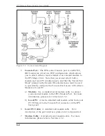
Page 7: ...o a local terminal or external modem as described in Section 4 3 Â Network Port An RJ45 Ethernet Port for connection to your TCP IP network The default IP Address is 192 168 168 168 for more information please refer to Section 5 3 1 and Section 4 4 Ã ACT Indicator Flashes to indicate activity at the Network Port Ä PWR Indicator Lights when Power is Applied to the Master Unit Note that this LED doe...

Page 8: ...cludes a master power switch the switched AC outlet a power inlet and a circuit breaker as described below À Master Power Switch This switch must be On in order for the IPS 15 to function Note that this switch is not used to set the On Off status of the switched outlets Á Switched AC Outlet A 115 VAC outlet that can switch up to 15 Amps If more than one switched outlet is required optional IPS 15 ...

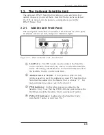
Page 9: ...nd or to other IPS Satellite Units Switching commands are sent from the Master Unit to the Satellite Unit s via the Link Ports Á Address Selector Switch A four position slider switch which is used to select the address for each IPS Satellite Unit Note that the address for the Master Unit is always 1 For more information please refer to Section 4 5 Â PWR Indicator Lights when power is applied to th...

Page 10: ...Outlet A 115 VAC outlet that can switch up to 15 Amps This outlet can be switched On Off or rebooted in response to commands issued at the IPS 15 Master Unit Á Power Inlet A 115 VAC inlet that supplies power for both command functions and the switched plug  Circuit Breaker 115 VAC 15 Amps 2 4 IPS Internet Power Switch User s Guide Figure 2 4 IPS 15 Satellite Unit Back Panel ...

Page 11: ...Connect the supplied power cable to the Power Inlet on the back panel of the IPS Master Unit Connect the other end of the power cable to an appropriate power supply CAUTION Make certain to review the safety precautions listed in Section 4 1 3 10BaseT Network Port Connect your 10Base T or 100Base T network interface to the IPS Network Port For more information please refer to Section 4 4 Note The I...

Page 12: ... for use with either a Modem or Local PC a Modem Use a standard serial modem cable to connect your external modem to the IPS s Modem Port For more information please refer to Section 4 3 2 b Local PC Attach a standard null modem cable from your PC COM port to the Console Port connector on the IPS back panel 6 Local PC Cable A standard null modem cable For a description of the port interface please...

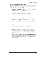
Page 13: ...Link Ports Optional A pair of RJ 11 Jacks which are used to connect the Satellite unit to the IPS Master Unit If additional Satellite units are to be installed the Link Port is also used to connect to the next Satellite unit in the chain 11 Connect Switched Device to Satellite Unit Optional Connect the power cable from your switched device to the Switched AC Outlet on the Satellite Unit s back pan...

Page 14: ... to your network and the PC being used to control the IPS must have a TCP IP network connection and a JavaScript enabled web browser The IPS includes a default IP Address and Subnet Mask This allows initial contact with the unit via network without first defining an IP address providing you are contacting the IPS from another node on the same subnet When installing the IPS in a working network env...

Page 15: ... the Off radio button for Plug one Next click the Apply button the IPS will display a screen indicating that the switch operation is in progress then return to the Plug Status Screen Note that the Status Indicator for Plug One now indicates that the plug is switched Off c Switch Outlet On Click the On radio button for Plug One Next click the Apply button the IPS will display a screen indicating th...

Page 16: ...tion or refer to Sections 4 and 5 for complete installation and configuration procedures 3 2 2 The Text Interface This section provides a brief description of the IPS 15 s Text Interface The Text Interface is a series of simple ASCII menus that are used to invoke commands and select configuration parameters The Text Interface can be used when the unit is contacted via Telnet modem or Local PC Note...

Page 17: ...ddress to an address that is on the same subnet as the IPS e g 192 168 168 xxx or access the IPS command mode via modem or Console Port and define Network Parameters as described in Section 5 3 3 b Modem Access Start your communications program and dial the number for the external modem The IPS Plug Status Screen Figure 3 3 should be displayed followed by the IPS command prompt c Console Port Acce...

Page 18: ...utlet ON To power the Switched AC Outlet ON go to the IPS command prompt type ON 1 and press Enter Power to the Switched Outlet will be switched ON 3 Exit Command Mode When you have finished testing the IPS unit type X and press Enter to exit from the Command Mode Note that it is recommended to always disconnect using the X command If the X command is not invoked at the end of a command session th...

Page 19: ...nt nameplate If you are not sure of the type of power service available please contact your local power company Reliable earthing grounding of this unit must be maintained Particular attention should be given to supply connections when connecting to power strips rather than directly to the branch circuit Check nameplate ratings to ensure that there is no overloading of supply circuits that could h...

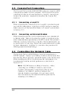
Page 20: ...lt 9600 bps no parity 8 data bits 1 stop bit The modem must be set to Auto Answer in one ring Please refer to the modem user s guide for more information Sections 5 3 1 describes the procedure for defining modem command strings 4 4 Connecting the Network Cable The Network Port is an RJ45 Ethernet jack for connection to a TCP IP network Connect your 10Base T cable to the Network Port Note that the ...

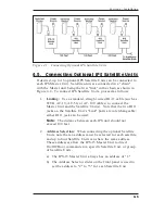
Page 21: ...llite Unit s Link ports are interchangeable either RJ11 jack can be used Note The distance between each IPS unit should not exceed 100 feet 2 Address Selection When connecting the optional Satellite Units note that an address must be selected for each satellite and up to four Satellite Units can share the same address These addresses allow the IPS 15 Master Unit to direct On Off Boot commands to a...

Page 22: ... recognize Satellite Units that are connected while the Master Unit is powered up until the Master Unit has been powered off and on If you attempt to address a command to a Satellite Unit that was connected after Power Up the IPS 15 Plug Status Screen will indicate that the Satellite Unit is not recognized After connecting Satellite Units to the IPS 15 Master Unit use the Master Power Switch on th...

Page 23: ...ll start up in System Mode or User Mode If the System Password is entered the System Mode will be active If the User Password is entered the User Mode will be active Both the System Password and User Password are defined via the General Parameters menu as described in Section 5 3 1 Notes If you wish to restrict user access to configuration menus you must define the System Password If the System Pa...

Page 24: ...he Text Interface is available via network modem or local PC The sections that follow describe the procedure for accessing the Web Browser Interface or the Text Interface 5 2 1 Accessing the Web Browser Interface In order to issue commands via the Web Browser Interface the IPS Master Unit must be connected to a TCP IP network and your PC or workstation must be equipped with a JavaScript enabled we...

Page 25: ...and your PC must include a communications program such as Hyperterminal Access Via Modem An external modem must be connected to the IPS Master Unit s Console Port and a phone line must be connected to the external modem Your PC Must include a communications program Access Via Local PC Your local PC Must be connected to the IPS Master Unit s Console Port The local PC must include a communications p...

Page 26: ...network that does not autosense for 10BaseT devices see Section 4 4 2 Password If the System Password has been defined the unit will display the Password Prompt Key in either the System Password or User Password and press Enter If the System Password has not been defined the prompt will not be displayed when the unit is accessed via the Text Interface Note that the Password feature is case sensiti...

Page 27: ...ion menu appears key in the number or letter for the parameter that you wish to define and follow the instructions in the resulting submenu Note the following To exit from a parameters menu press the Esc key The following sections describe the options and parameters that are available in each of the configuration menus Please note that essentially the same selection of parameters and options are a...

Page 28: ...ult undefined Notes If the System Password is not defined then the IPS will always start up in System Mode and configuration functions will then be available to anyone who accesses the Command Mode When defining passwords via Web Browser Interface you must re key the desired password in the Confirm Password field When defining passwords via the Text Interface the submenu will also ask you for conf...

Page 29: ...h can be sent out the serial Console Port to initialize an external modem If the Serial Port Mode is set to Console the modem initialization string will not be sent For more information on initialization commands refer to the user s guide for your modem Default ATE0M0Q1 C1 D2S0 1 Baud Rate The Baud Rate for the IPS Master Unit s Console Port Default 9600 bps No Parity 8 Data Bits 1 Stop Bit Note W...

Page 30: ...trol switching without human intervention For more information please refer to Section 6 5 Default Off Note When this option is enabled security functions are suppressed and users are able to access System Level menus and control plugs without entering a password If security is a concern and the Automated Mode is required it is recommended to use the IP Security feature Section 5 3 3 1 to restrict...

Page 31: ...refer to Section 4 5 Web Browser Interface Click the Setup button to access the configuration menus then click the Plug Parameters button The Plug Parameters Menu will be displayed as shown in Figure 5 5 Text Interface Type P n and then press Enter Where n is the number or name of the plug you wish to configure The Plug Parameters Menu will be displayed as shown in Figure 5 6 5 9 Section 5 Configu...

Page 32: ...Parameters button The Web Parameters Menu will be displayed as shown in Figure 5 7 Text Interface Type N and press Enter The Network Parameters Menu will be displayed as shown in Figure 5 8 Notes Although both the Web Browser Interface and Text Interface both allow configuration of the same network parameters note that when parameters are defined via the Text Interface the IP Security feature is c...

Page 33: ...ss Displays the unit s MAC Address Please note that this item only displays the assigned MAC Address and cannot be used to redefine the address 5 11 Section 5 Configuration Figure 5 7 Network Parameters Menu Web Browser Interface NETWORK PARAMETERS 1 IP Address 65 106 93 120 2 Subnet Mask 255 255 255 0 3 Gateway Address 65 106 93 97 4 Send MSS 1460 5 IP Security MAC Address 00 0c 67 23 45 67 Enter...

Page 34: ...Each Mask Action prompt defines the permit deny action for the corresponding mask b Masks are listed in order of ascending priority Mask 1 has the lowest priority Mask 5 has the highest priority c Masks have a cumulative effect high priority masks supersede the effect of lower priority masks d Each IP Address consists of a series of four eight bit numbers The number 255 is used as a wild card Exam...

Page 35: ... 255 255 255 make certain that at least one higher priority mask permits access by your IP address 5 3 4 The Telnet Parameters Menus The Telnet Parameters Menus are used to enable disable Telnet access to the IPS command mode and select the default TCP port for Telnet connections Web Browser Interface Click the Setup button to access the configuration menus and then click the Telnet Parameters but...

Page 36: ...e unit via Telnet Default On Port Number Selects the port number that will be used for Telnet connections Default 23 5 3 5 Web Server Parameters Menus The Web Server Parameters Menus are used to configure the IPS s internal web server which allows the unit to be operated via the Web Browser Interface 5 14 IPS Internet Power Switch User s Guide Figure 5 10 Telnet Parameters Menu Web Browser Interfa...

Page 37: ...ia both the Web Browser Interface and the Text Interface Service Enables Disables the IPS s Web Server Note that when the Web Server is disabled you will not be able to communicate via the Web Browser Interface Default On Port Number Sets the TCP IP Port Number The Port Number can be set to any valid number except 23 this is because 23 is the default port number that is used for communication with...

Page 38: ...n Section 7 this provides quick recovery in the event that the unit is accidentally reset to default parameters and also allows you to copy parameters to other IPS 15 units when several Master Units need to be configured with the same parameters Notes After new Parameters have been applied the IPS will display a Save prompt In the Web Browser Interface this prompt appears when you leave the config...

Page 39: ...llite unit is assigned to one of four possible Plug Numbers or Zones Zones are determined by the setting of the Address Selector Switch on each individual satellite unit For example all satellite units that have their Address Selector Switch set to 2 are defined as Plug 2 or Zone 2 all satellite units that have their Address Selector Switch set to 3 are defined as Plug 3 or Zone 3 and etc By group...

Page 40: ... Status Screen Figure 6 1 lists the current status of the IPS 15 s Switched Outlet s and provides a series of radio buttons which are used to control On Off Boot switching of the outlet s If one or more optional IPS Satellite Units have been connected to the IPS Master Unit then the Plug Status Screen will indicate the On Off status of each plug zone If your installation includes only the IPS Mast...

Page 41: ...itch one or more plugs Off click the Off radio button next to the desired plug s and then click on the Apply button a To switch all Plugs Off click on the Off radio button in the All Plugs line and then Click Apply b The IPS will display a screen which indicates that the switching operation is in progress and then return to the updated Plug Status Screen which should now show the selected plugs in...

Page 42: ...very time that a command is successfully executed Note however that if the Automated Mode is enabled See Section 6 5 the Plug Status Screen will not be redisplayed after each command is executed 6 3 2 Boot On Off Commands Text Interface These commands are used to Boot or toggle the On Off status of the IPS s switched plug s Plugs may be specified by name or number Notes Wait for the IPS prompt to ...

Page 43: ...without displaying the Sure prompt include the Y option in the command line The Y option is entered immediately following the command argument For example ON ROUTER Y or BOOT 2 Y 6 5 Section 6 Operation Internet Power Switch v1 01 Site ID WTI Internal Test Unt v 1 01 Display Configuration H Display Help Screen G View Set General Parameters S Display Plug Status P n View Set Plug Parameters SN Disp...

Page 44: ...d by a colon For example to switch plugs 1 through 3 On enter the following ON 1 3 Enter 4 All Plugs To apply a command to all plugs the IPS Master Unit plus each connected Satellite Unit enter an asterisk in place of the name or number For example to Boot the Master Unit Plug and all plugs on connected satellite units enter the following BO Enter 6 4 Logging Out of Command Mode When you are finis...

Page 45: ...ser Interface can still be used to invoke On Off Boot commands Notes When Automated Mode is enabled all IPS password security functions are disabled and users are able to access System Level command functions including the configuration menus and control plugs without entering a password If you need to enable the Automated Mode but want to restrict network access to IPS configuration menus it is r...

Page 46: ...ion to the command driven functions available via the Web Browser Interface and Text Interface the IPS s switched plugs can also be toggled On and Off manually To manually toggle plug s On or Off press the Manual Control Button and hold it down for approximately one second the corresponding plug s will be toggled On or Off If desired the Button Mode Parameter which is accessed via the General Para...

Page 47: ...ch allows downloading of ASCII files Note Although this function is available only via the Text Interface parameters that have been defined via the Web Browser Interface will also be sent to the ASCII file 7 1 Sending Parameters to a File 1 Start your communications program and access the IPS command mode using the System Level Password 2 When the IPS command prompt appears type DL and press Enter...

Page 48: ...load the file with the saved parameters If necessary key in the file name and directory path 5 When the upload is complete make certain to terminate the communications program s upload mode Note The current On Off status of each IPS plug will not be saved or restored However the selected default On Off setting for each plug will be saved and restored When the configuration file is sent to the IPS ...

Page 49: ...A Interface Descriptions A 1 Console Port Interface A 2 Straight Wired RJ11 Cables Apx 1 Figure A 1 Console Port Interface Figure A 2 Straight Wired RJ11 Cables ...

Page 50: ...Coding Serial ASCII 8 Bits No Parity Physical Environmental Size Height 1 75 4 5 cm Depth 7 00 17 8 cm Width Master Unit 5 80 14 7 cm Satellite Unit 4 60 11 7 cm Weight 4 lbs Shipping Weight Temperature Operating 32F to 122F 0C to 50C Humidity 10 90 RH Ordering Information IPS 15M Master Control Unit 115VAC 15 Amps IPS 15S Satellite Unit 115 VAC 15 Amps IPS 15R 19 Rack Mount Tray 1 RU Mounts Maste...

Page 51: ...e unit its serial number and a description of its symptoms If the unit should need to be returned for factory repair it must be accompanied by a Return Authorization number from Customer Service WTI Customer Service 5 Sterling Irvine California 92618 Toll Free Service Line 1 888 280 7227 Local Phone 949 586 9950 Service Fax 949 457 8138 Email service wti com Apx 3 ...

Page 52: ...tion and descriptions contained herein are the property of Western Telematic Inc Such information and descriptions may not be copied disseminated or distributed without the express written consent of Western Telematic Incorporated Copyright Western Telematic Inc 2002 2003 All right reserved Printed in the United States of America February 2003 WTI Part Number 13301 Rev B Apx 4 IPS Internet Power S...

Page 53: ...sable Telnet 5 13 to 5 14 Downloading Parameters 7 1 Duplex Mode 5 8 E Error Messages 6 8 Ethernet Port 2 1 3 1 4 2 External Modem 4 2 5 7 F Firmware Setup 5 1 to 5 16 Front Panel Master Unit 2 1 Satellite Unit 2 3 G Gateway Address 5 11 General Parameters Menu 5 5 to 5 8 H Hardware Installation 4 1 to 4 4 Help Screen 6 4 I Inactivity Timeout 5 8 Installation 4 1 to 4 4 Interface Description Apx 1...

Page 54: ...ng Plugs 6 2 to 6 3 Reset Parameters 5 8 Restoring Parameters 7 2 RJ11 Cables 3 3 Apx 1 S Satellite Unit 2 3 to 2 4 4 3 to 4 4 Address 2 3 Saving Parameters 5 16 7 1 Security 5 1 5 12 to 5 13 Segment Size 5 11 Selector Switch 2 3 4 3 to 4 4 6 1 Send MSS 5 11 Serial Port 2 1 3 2 4 2 Serial Port Mode 5 7 Service 5 14 Web Server 5 15 Site I D Message 5 7 Specifications Apx 2 Straight Wired Cables 3 3...

Page 55: ......
Page 56: ...5 Sterling Irvine California 92618 949 586 9950 Toll Free 1 800 854 7226 Fax 949 583 9514 http www wti com ...
Reviews: