background image

6.

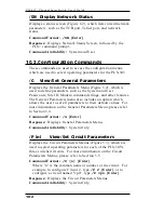
The Status Screens

The PLS Status Screens are used to display current conditions of

the three switched A/B circuits and the network interface. There

are two status screens; the Circuit Status Screen (/S), and the

Network Status Screen (/SN).

6.1. The Circuit Status Screen

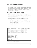
The Circuit Status Screen lists the current A/B settings for the

PLS-345's three switched circuits, and also summarizes user-

selected parameters, such as Command Echo, Inactivity Timeout,

and Command Confirmation.
As shown in Figure 6.1, the Circuit Status Screen lists the

following items:

1.

Site ID Message:

The currently defined Site ID message.

Note that the site ID message is defined via the General

Parameters Menu (/G).

2.

Ckt #:

The circuit numbers for the PLS's three A/B

circuits.

6-1

Physical Layer Switch v1.00

Site ID: PLS-345_TEST_IRVINE_CALIFORNIA

CKT# | From

| To

| POS | MON | Default |

-----+------------------+------------------+-----+-----+---------|

1

| COMMON_LINE_1

| LINE_B1

| B |

|

A

|

2

| COMMON_LINE_2

| LINE_A2

| A | * |

A

|

3

| COMMON_LINE_3

| LINE_A3

| A | * |

A

|

-----+------------------+------------------+-----+-----+---------|

Command Echo:

On

Inactivity Timeout:

30 Min

Command Confirmation:

On

Automated Mode:

Off

Monitor Mode:

On

Monitor Input Level:

1 - High

"/H" for help.

Figure 6.1: The Circuit Status Screen

Summary of Contents for PLS-345

Page 1: ...WTI Part No 13236 Rev A PLS 345 Physical Layer Switch User s Guide...

Page 2: ......

Page 3: ...n should be given to supply connections when connecting to power strips rather than direct connections to the branch circuit Rack Mount Installation When installing this device in an instrument rack t...

Page 4: ...t block the ventilation slots on the instrument cover If the device is installed on sliders check the unit when seated all the way into the rack to make certain that ventilation slots are not blocked...

Page 5: ...Menu Conventions 5 4 5 4 Defining General Parameters 5 5 5 5 Circuit Parameters 5 8 5 6 Network Parameters 5 9 5 6 1 Implementing IP Security 5 11 5 7 The Monitor Mode 5 13 5 7 1 Hardware Configuratio...

Page 6: ...Back Panel 2 2 3 1 The Circuit Status Screen 3 3 3 2 The Command Help Screen System Mode 3 4 5 1 The Circuit Status Screen 5 3 5 2 The General Parameters Menu 5 5 5 3 The Circuit Parameters Menu 5 8 5...

Page 7: ...e allows the PLS 345 to monitor an external RS 232 line or contact closure input and automatically switch selected A B paths Easily definable parameters allow the user to select the monitor signal tri...

Page 8: ...oring for Automatic Switching Retains Selected Position with Power Off Independent 10Base T Ethernet Control Port Independent RS 232 Console Port Independent Modem Port for Out of Band Management Typo...

Page 9: ...Press the B button to switch the common line for Circuit 1 to the B connector The LED adjacent to the Selector Button will light when Line B is selected Note Each circuit can either be manually switch...

Page 10: ...tors for the Circuit 1 common line and A and B lines A A Connector and Status LED The status LED will light when line A is selected B B Connector and Status LED The status LED will light when line A i...

Page 11: ...n RS 232 line or a contact When properly configured the PLS 345 can perform A B switching based on the signal level at either an RS 232 Line or a contact connected to the Monitor Input Connector For m...

Page 12: ...2 4 PLS 345 Physical Layer Switch User s Guide...

Page 13: ...ct Network Cable External Modem or PC In order to configure and control the PLS you must first decide how you will communicate with the unit via network modem or local PC a Network Connect your 10Base...

Page 14: ...One Stop Bit No Parity Although PLS parameters can be easily redefined for this Quick Start procedure only it is recommended that you configure your communications program to accept the default param...

Page 15: ...yed followed by the PLS command prompt 5 Review Help Menu At the PLS command prompt Type H and press Enter to display a help menu Figure 3 2 which provides a basic listing of PLS commands 3 3 Section...

Page 16: ...feature closes the session In this case further access to the PLS command mode will not be allowed until the current session times out This completes the introductory overview of the PLS Please procee...

Page 17: ...ffect on overcurrent protection and supply wiring 4 2 Initialization If you are reinstalling a PLS 345 unit that has been previously installed or if you wish to ensure that the PLS 345 is starting out...

Page 18: ...PLS features a 10Base T Interface When connecting the PLS to a 100Base T interface note that most router switches will autosense to determine if the device is 100Base T or 10Base T and then configure...

Page 19: ...mpt whenever the unit is contacted via the Console Port Modem Port or Network Port The password entered at this prompt determines whether the unit will start up in System Mode or User Mode If the Syst...

Page 20: ...ned the password prompt will be displayed Key in your System Password or User Password and press Enter The PLS 345 will display the Status Screen Figure 5 1 followed by the PLS command prompt Note In...

Page 21: ...may mean that either the IP Security feature see Section 5 6 1 has denied the connection or the unit is operating on a 100BaseT network that does not autosense for 10BaseT devices see Section 4 4 iii...

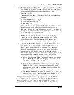
Page 22: ...the item and press Enter To exit from a menu press Esc at any time Parameters defined up to that point will be saved To display the Help Screen type H Enter The y option can temporarily suppress the...

Page 23: ...nter and follow the instructions in the submenu Up to 16 characters case sensitive Default undefined Notes If the System Password is not defined the password prompt will not be displayed and the PLS w...

Page 24: ...n the initialization string please refer to the user s guide for your external modem Make certain that the external modem is set to auto answer in one ring Up to 32 characters Default ATE0M0Q1 C1 D2S0...

Page 25: ...the PLS will execute the A B D T and X commands without displaying the confirmation prompt status screen or confirmation messages When Automated Mode is enabled the password prompt will also be suppr...

Page 26: ...switching commands can be invoked using the number or common name of the desired A B circuit To assign a Common Name type 1 press Enter and follow the instructions in the submenu Up to 16 characters D...

Page 27: ...ommunicate with the PLS via network the IP Address Subnet Mask and Gateway Address should be defined using the Network Parameters Menu Note that although the PLS features a default IP Address which al...

Page 28: ...55 255 0 3 Gateway Address Defines the Gateway Address for the PLS unit Type 3 press Enter and follow the instructions in the submenu Default undefined 4 IP Security Sets up the IP Security feature as...

Page 29: ...ith the selected permit deny action for each mask a Each Security Mask prompt is used to define a specific IP address or range of IP addresses Each Mask Action prompt is used to define the permit deny...

Page 30: ...1 5 Security Mask 1 255 255 255 255 Mask 1 Action Deny Security Mask 2 192 255 255 255 Mask 2 Action Permit Security Mask 3 192 1 1 5 Mask 3 Action Deny Since 255 is a wild card Mask 1 blocks all IP...

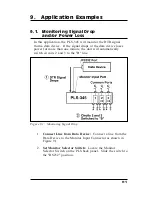
Page 31: ...Input Connector b Contact Connect a line from the contact that you wish to monitor to the Monitor Input Connector c Ground Line Connect an appropriate ground line to the Ground Connector on the PLS b...

Page 32: ...et at B then the monitored line goes low the selected A B circuit s will be switched to Line B Default B 4 Delay Period Determines how long the monitored line must remain at the target level Item 2 in...

Page 33: ...s three switched A B circuits will be controlled by the Monitor Mode Note that when this item is used to enable the Monitor Mode at a given A B circuit then the Circuit Status Screen will display an...

Page 34: ...red it is recommended to save parameters to an ASCII file as described in Section 8 This allows quick recovery in the event that the unit is reset to default parameters or if the configuration is acci...

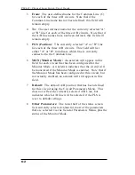
Page 35: ...and Command Confirmation As shown in Figure 6 1 the Circuit Status Screen lists the following items 1 Site ID Message The currently defined Site ID message Note that the site ID message is defined via...

Page 36: ...s field for each circuit that has been configured for the Monitor Mode An asterisk indicates that the circuit will be monitored if the Monitor Mode is enabled Note that if the Monitor Mode has been co...

Page 37: ...he PLS Network Interface card is listed in the second line of the Network Status Screen adjacent to the text which reads NETWORK STATUS 3 TCB Transmission Control Block Always 1 a SRC PORT Source Port...

Page 38: ...6 4 PLS 345 Physical Layer Switch User s Guide...

Page 39: ...s a signal received via the Monitor Input Port and switches one or more A B Circuits according to user defined parameters These methods are discussed in the sections that follow 7 1 Manual A B Switchi...

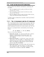
Page 40: ...d the B command will switch one or more circuits to the B line Both the A command and the B command use the following format A n Enter or B n Enter Where n is one of the following Switch One Circuit T...

Page 41: ...r user defined default A B positions Default A B positions are defined via the Circuit Parameters Menus P n When the D command is invoked the PLS will set all three circuits to their default A B posit...

Page 42: ...switching in response to signal level changes at the monitor port on the instrument back panel The Monitor Mode can be set to monitor a Contact or an RS 232 Line For more information on the Monitor M...

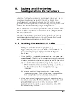
Page 43: ...File 1 Start your terminal emulation program e g HyperTerminal and access the PLS Command Mode If the password prompt is displayed enter the System Password 2 When the PLS command prompt appears type...

Page 44: ...text file to the PLS When the terminal program is finished with the upload make certain to terminate the Upload mode Notes If the PLS detects an error in the parameters file it will respond with the...

Page 45: ...oses power for more than one minute the unit will automatically switch circuits 2 and 3 to the B line 1 Connect Line from Data Device Connect a line from the Data Device to the Monitor Input Connector...

Page 46: ...rn to their original positions if the monitored line goes high again then this item would be enabled f Item 6 Circuits to Switch Enable the Monitor Mode at circuits 2 and 3 4 Set Circuit Parameters Fr...

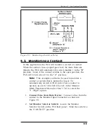
Page 47: ...d to monitor a contact or switch that is normally closed To automatically switch A B circuits when a contact is opened use item 3 Switch if Level in the Monitor Mode Parameters Menu Section 5 7 2 to s...

Page 48: ...if the signal goes high again and remains high for one minute f Item 6 Circuits to Switch Enable the Monitor Mode at circuit 1 4 Set Circuit Parameters From the PLS command prompt type P 1 Enter to di...

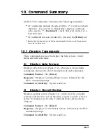
Page 49: ...status and network status H Display Help Screen Displays a Help Screen Figure 3 2 which lists all available commands along with a brief description of each command Command Format H Enter Response Disp...

Page 50: ...arameters menu also includes an option which allows the user to set all parameters to their default values For more information on the General Parameters Menu please refer to Section 5 4 Command Forma...

Page 51: ...nput Port For more information on the Monitor Mode please refer to Section 5 7 Command Format M Enter Response Displays Monitor Mode Parameters Menu Command Availability System Only DL Download Config...

Page 52: ...itched waits for user confirmation unless suppressed switches target circuit s to A then displays Status Screen Command Availability System and User B n Switch Circuit n to Line B Switches the target...

Page 53: ...ault positions and then displays Status Screen Command Availability System and User T Reset Network Interface Terminates the Telnet connection and then resets the network interface Note In order to pr...

Page 54: ...nd is not invoked at the end of a command session then PLS will not exit from command mode until the No Activity Timeout feature closes the session In this case further access the PLS command mode wil...

Page 55: ...A Interface Descriptions A 1 Console Port Interface A 2 Modem Port Interface Apx 1 Figure A 1 Console Port Interface Figure A 2 Modem Port Interface...

Page 56: ...A 3 Common Ports and A B Ports Apx 2 PLS 345 Physical Layer Switch User s Guide Figure A 3 Common Ports and A B Ports...

Page 57: ...ircuit number or name Network Port 10BaseT Ethernet RJ45 Console Port RS 232 DB 9M DTE pinout Coding Serial ASCII 8 bits no parity Data Rate 2400 9600 19 2K 38 4K bps Modem Port RS 232 DB 9M DTE pinou...

Page 58: ...27 Customer Service Fax 949 457 8138 E mail service wti com Trademark and Copyright Information WTI and Western Telematic are trademarks of Western Telematic Inc All other product names mentioned in t...

Page 59: ...6 Common Line 4 2 Common Name From 5 8 Configuration 5 1 to 5 16 Restore 8 2 Save 8 1 Configuration Commands 10 2 to 10 3 Connectors 2 2 Console Port 2 3 4 2 5 2 Apx 1 Contact 9 3 Control Commands 10...

Page 60: ...ers 5 1 to 5 16 Restore 8 2 Save 8 1 Passwords 5 1 System 5 5 User 5 6 Permit Access 5 11 Position 6 2 Power Components 2 3 Q Quick Start 3 1 to 3 4 R RDY Indicator 2 2 Reset 4 1 Reset Network Interfa...

Page 61: ......
Page 62: ...5 Sterling Irvine California 92618 949 586 9950 Toll Free 1 800 854 7226 Fax 949 583 9514 http www wti com...

Reviews: