4.2.
Gang Switch Control
This method allows the Master Select Switch to control A/B
selection at all connected Switch Modules. In addition, switching
can also be controlled by a remote switch connected to the Control
Module's Remote Port. To configure a Switch Module for Gang
Switch Control, proceed as follows:
Note:
When multiple RAB-14A banks are daisy chained, the
Master Select Switch on each Control Module will
effect all down-line banks. For example, if your
installation includes six banks, the Master Select
Switch on bank four can control Switch Modules in
banks four, five, and six.
1. Carefully remove the Switch Module from the RAB-14A
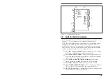
rack and locate the jumpers as described in Figure 3.1.
2. Place Jumper J3 in the “GANG” position.
3.
Disable Local A/B Switch (Optional):
To disable the Local
A/B Switch for this Switch Module, remove Jumper J4.
When J4 is removed, the module will continue to respond to
the Master Select Switch, but the Local A/B Switch will
have no effect.
4. Carefully replace the Switch Module in the rack. Place
Local A/B Switch in the middle position. The “X” LED
should light.
5.
External Remote Switch (Optional):
Connect an
appropriate remote switch to the Remote Port on the Master
Bank Control Module. Please refer to Appendix A for a
description of the Remote Port.
6. Use the Master Select Switch to change A/B channels at all
selected switches. When the Master Select Switch is placed
in the “A” position, all Switch Modules configured for Gang
Switch Control should indicate that channel “A” is selected.
4-2
RAB-14A User’s Guide

