5.4.
Test Switch Modules
To perform a brief test, which checks all Switch Modules for
proper operation and response, make certain all Local A/B
Switches are set in the middle (X) position, and then type
^AT
[Enter]
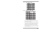
. The Test Result Screen shown in Figure 5.1 will be
displayed.
Note:
·
Figure 5.1 shows an RAB-14A installation which
includes 14 banks. If your installation includes less
than 14 banks, result lines for additional banks will
not be displayed.
·
If Local A/B Switches are
not
set in the “X”
position, the Test Result Screen will list “NO
RESPONSE” for those modules.
Caution:
Do not invoke the Test Command while data is
flowing through the unit. As a part of the test
routine, each Switch Module will be briefly toggled
between “A” and “B”. If the test is performed while
Switch Modules are in use, data may be lost or
corrupted.
5-4
RAB-14A User’s Guide
TEST
BANK|
CHANNEL(S)
--------------------------
1
| GOOD
2
| GOOD
3
| GOOD
4
| GOOD
5
| GOOD
6
| GOOD
7
| GOOD
8
| GOOD
9
| GOOD
10 | GOOD
11 | GOOD
12 | GOOD
13 | GOOD
14 | GOOD
Figure 5.2: The Test Screen (14 Banks Shown)


