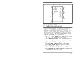
A.2.1.
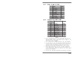
Ports “A” and “B” (DTE)
Pin
Signal
Note
1
F Ground
1
2
Data, Output
3
Data, Input
4
RTS, Output
5
CTS, Input
6
DSR, Input
7
Signal Ground
2
8
DCD, Input
20
DTR, Output
5
12
Remote, Input
3
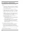
A.2.2.
Common Port (DTE or DCE)
Pin
Signal
Note
DTE
DCE
1
1
F Ground
1
3
2
Data, Input
2
3
Data, Output
5
4
RTS, Input
4
5
CTS, Output
5
24
6
DSR, Output
7
7
Signal Ground
2
20
8
DCD, Output
5
8
20
DTR, Input
12
12
Remote, Input
3
25
25
A/B Status, Output
4
Notes:
1.
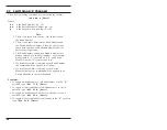
Pin 1 is common to Ports “A”, “B”, and Common. Jumper J1 on
the Switch Module board is used to connect Pin 1 at Ports “A”, “B”,
and Common to the logic ground.
2.
Pin 7 (logic ground) is common to Ports “A”, “B”, and Common.
3.
Pin 12 on Ports “A”, “B”, and Common is the RS232 input used to
switch the channel if configured for local control using jumper J3
(select one only). Pin 12 High (+) or open = A, Low (-) = B.
4.
Pin 25 on the Common Port is an RS232 output which indicates
Switch Module Status. High = B, Low = A. Pins 12 and 25 are
used to switch the port and drive the A/B LEDs when connecting to
the remote switch module.
5.
The DTR, CTS, and DCD outputs can be forced high (+10 VDC) by
Apx-3
Appendices

