Page 3
1. Introduction
This Quick Start Guide describes a simplified installation procedure for the
RPC-4850 Series hardware, which will allow you to communicate with the unit in order to
demonstrate basic features and check for proper operation. Note
that this Quick Start Guide does not provide a detailed description
of unit configuration or discuss advanced operating features in
detail. For more information, please refer to the User’s Guide,
which can be found on our web site at the address below, or by
scanning the QR Code to the right.
http://www.wti.com/uguides
2. Hardware Installation
Apply Power to the RPC
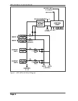
Refer to power rating nameplate on the back panel, and then connect the RPC unit to an
appropriate power source as shown in Figure 1 or Figure 2.
The RPC features two separate DC inputs; connect power cables to the unit's Circuit
"A" and/or Circuit "B" terminal blocks, then connect the cables to an appropriate power
supply. Note that it is not necessary to connect power to both input circuits; either
circuit will supply power for operation and control functions. However, when power is
connected to both circuits, this allows the second circuit to function as a back-up in the
event of a power outage.
Note that each individual output circuit will support up to 15 Amps maximum, and that
the total for all eight circuits cannot exceed 50 Amps.
The ON LED should light, and the RDY LED should begin to flash. This indicates that
the RPC is ready to receive commands.
Connect your PC to the RPC
The RPC can either be controlled by a local PC, that communicates with the unit via
cable, controlled via external modem, or controlled via TCP/IP network. In order to
switch circuits On/Off or select parameters, commands are issued to the RPC via either
the Network Port or Console Port. Note that it is not necessary to connect to both the
Network and Console Ports, and that the Console Port can be connected to either a local
PC or External Modem.
•
Network Port:
Connect your 10Base-T or 100Base-T network interface to the RPC
Network port.
•
Console Port:
Use the null modem cable supplied with the unit to connect your PC
COM port to the RPC Console (RS232) Port.
•
External Modem:
Use a standard AT or modem cable to connect your external
modem to the RPC's Console (RS232) Port.


