2
I
N
S
T
A
L
L
A
T
I
O
N
When you begin to install your
Wunder- Bar
® Mechanical Flex Hose bar
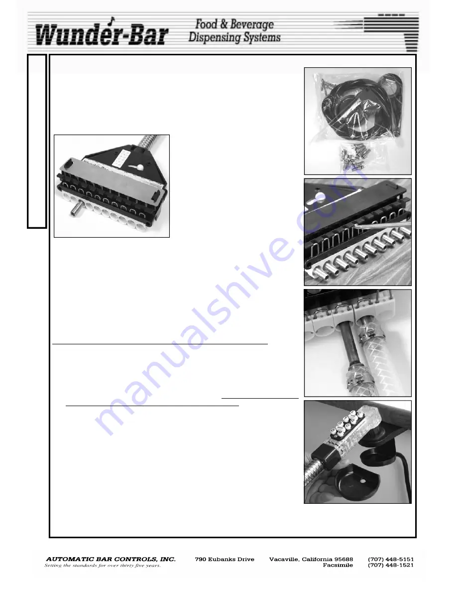
dispenser, you will notice that all necessary mounting hardware, a hose
hanger, a drip cup, a drain tube, and the appropriate number of stainless
steel input fittings are included with each dispenser (
Fig.1
).
The input fittings are installed in the product manifold of the dispenser.
These input fittings are held in place by kwik klips. To remove input fittings,
pull up on kwik klip just far enough to allow removal of the fittings (
Fig.2
). (It
is not necessary to remove the kwik klip entirely).
1/4” straight Input Fittings are included
with all new
Wunder-Bar®
Post-Mix
Beverage and Juice Dispensers unless
custom “Fitting Sets” are ordered. In-
put fittings are available in straight, 90
degree, and 45 degree configurations
with either 1/4”, 5/16”, 3/8", or 1/2"
barbed ends. 3/8” and 1/2” Input Fit-
tings are available in two lengths:
“short” and “long” (
Fig.3
) to allow the
two lengths to be installed “staggered”
to accommodate braided tubing.
To make a tubing connection; remove the input fitting, secure the tubing to
the fitting with a ferrule or Oetiker clamp, re-install fitting into correct posi-
tion on the manifold, push the kwik klip down fully to lock the input fitting
into position. The letters and numbers on the manifold label correspond to
the button positions on the dispensing handle.
Use the two, 2" stainless steel wood screws, provided as part of the mount-
ing hardware package, to secure the tube collector/manifold assembly to
the underside of the bar. (A Kwik Mount kit is also available as an optional
item). It is recommended that a screw be placed in both the tube collector
and the brix manifold to prevent unwanted flexing.
SANITARY DRIP CUP (Fig.4) INSTALLATION INSTRUCTIONS:
1. Position the PH10-121 (Drip Cup Holder) into the recess located under the
PM10-40 (Hose Hanger) and align the three matching mounting screw holes.
2. Position the combined PH10-121 and PM10-40 under the countertop, in the
desired mounting location, with the alignment line lined-up with the front edge
of the countertop.
3. Install three PM10-65 (#10 x 3/4” Phillips, Pan Head Screws) through the three
mounting holes and into the countertop, completely, until no screw threads are
visible or exposed below the screw hole mounting bosses.
4. Install one end of the PH10-106 (6’ Drain Tube) onto the PH10-121’s (Drip Cup
Holder) drain nipple, fully.
5. Extend the other end of the PH10-106 (6’ Drain Tube) to the floor sink or drain.
Do not install Drain Tube end into the ice bin or sink drain.
6. Install the PM10-76 (Grommet) into the PM10– 40 (Hose Hanger).
7. Install the PH10-122 (Drip Cup Insert) into the PH10-121 (Drip Cup Holder)
After all connection are made, turn on water supply, carbonator, C02,
and BIB pumps. CHECK ALL DISPENSER AND SYSTEM FITTINGS
CONNECTIONS FOR LEAKS IMMEDIATELTY!
ATTENTION!
The POST-MIX DISPENSER’S water supply line must be connected to the potable water supply with
adequate backflow prevention to comply with federal, state, and local codes.
Fig.1
Fig.2
Fig.3
Fig.4
MARK 4 MANUAL
www.wunderbar.com
Summary of Contents for Mark 4
Page 15: ...15 15 www wunderbar com ...
Page 16: ...16 16 www wunderbar com ...
Page 17: ...17 17 www wunderbar com FR 73 ...
Page 18: ...18 18 www wunderbar com ...
Page 19: ...19 20 www wunderbar com ...
Page 20: ...20 19 www wunderbar com ...
Page 21: ...21 21 www wunderbar com ...
Page 22: ...22 www wunderbar com 22 FR 73 ...
Page 23: ...23 23 www wunderbar com ...
Page 24: ...24 24 www wunderbar com ...
Page 25: ...25 25 www wunderbar com ...
Page 26: ...26 26 www wunderbar com ...


