Anbauanleitung
Fitting Instructions
Istruzione
Bestell Nummer / Part Number / Codice: 8600465
R 1200 GS Micro Flooter Zusatzscheinwerfer / Auxiliary Lights / Fari supplementari
1.
Rimuovere prima la sella e scollegare il cavo nero
negativo (-) della batteria.
2.
Rimuovere i fianchetti dal serbatoio svitando le 2
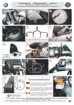
viti a lato ed una inferiore nella parte interna (figura A).
3. Smontare le 3 viti TORX (figura B) e rimuovere completamente
entrambe le coperture del serbatoio.
4. Staccare nella parte destra i due tubi spurgo e rimuovere il
tubo benzina premendo il bottone dell’attacco rapido (figura
C).
5. Rimuovere con la stessa procedura il tubo nella parte sinistra
e scollegare la presa della pompa benzina (figura D).
6. Smontare i due bulloni del serbatoio e rimuoverlo.
7. Assemblare i due supporti faro con delle viti a testa svasata
M5,rondelle a U e dadi. Incollare i gommini alla parte inferiore
del supporto faro come illustrato a figura E.
8. Rimuovere il supporto originale dai fari, quindi montare i fari
al supporto d’alluminio utilizzando due distanziali 11,5mm,
una vite 6x20mm alla parte esterna, una vite 6x25mm alla
parte interna, rondelle e dadi.
9. Rimuovere l’inserto e scollegare gli attacchi. Svitare la vite
del supporto frecce, girare il braccetto di 180° e rimuoverlo.
Svitare la vite dell‘attacco del faro (figura F)
10. Posizionare l’adattatore sul braccetto della frecce. Posizionare
il distanziale 8mm all’accesso dove il faro è stato montato
e montare il supporto principale del faro al veicolo con una
vite 6x45mm, e la freccia utilizzando una vite Mx25mm con
rondella e rondella a U fra adatattore e supporto del faro cen-
trale. (figura H). Serrare i bulloni e ripetere questa procedura
alla parte opposta.
11. Smontare la vite TORX posteriori del supporto specchi, scol-
legare gli attacchi del cavo e montare l’interruttore con una
vite M5x30, rondella e distanziale piccolo al manubrio (figura
I).
12. Installare il relè nella parte sinistra con fascette ai cavi esistenti
(figura J), portare il cavo partendo dal relè all’interruttore se-
guendo la linea dei cavi originali. Collegare i due cavi. Portare
i cavi verso il faro, prima verso il faro sinistro e da li al faro
destro.
13. Portare il cavo nero (dall’interruttore) all’attacco elettrico del
faro. Collegare il cavo nero con il cavo blu- grigio del faro di
posizione (figura K) attraverso l’attacco rapido. Montare il
faro.
13b.
Note:
se si possiede una presa di bordo originale (BMW
71 60 7 685 121), il cavo nero alternativamente può essere
collegato col cavo rosso (N). È anche possibile collegare i
fari al cavo Accessori Outlet della BMW (71 60 7 685 624,
figura M). In entrambi i casi si spengono 1 minuto dopo aver
estratto la chiave d’accensione (consigliamo comunque di
spegnere prima i fari!).
14. Isolate tutti i collegamenti con guaina autorestringente (figura
L). Riscaldandola con un apposito phon in modo da isolare
perfettamente i collegamenti del faro. Inserire il cavo fra
carena e supporto faro. Se utilizzate un faro unico, isolate
il secondo cavo con lo stesso procedimento della guaina
autorestringente e posizionatelo al di sotto della carena (Fig
O).
15. Fissare tutti i cavi con fascette per evitare lo strofinamento e
lo schiacciamento. Collegare il cavo rosso dal relè al positivo
(+) della batteria e quello marrone al negativo (-).
16. Rimontare il serbatoio, le carene laterali e la sella al motovei-
colo. Regolare la posizione del faro e controllare nuovamente
tutti i fissaggi.
Controllare la funzione del faro e delle frecce prima
di mettersi alla guida del mezzo!!
1.
Remove the seat(s) and disconnect the negative (-) wire
of the battery.
2.
Remove both left and right tank panels by removing the
three quick connect fasteners on each side. (Image A)
3. Remove the 3-Torx screws (Image B) from each aluminum side panel
and remove the panels completely from the bike.
4. On the right side, carefully pull off the vent hoses and disconnect
the fuel line by depressing the side of the quick connector.(Image C)
5. On the left side, disconnect the fuel line in the same manner and
unplug the electrical connector. (Image D) Note that the electrical
plug has a locking tab.
6. Remove the two (allen) tank mounting bolts and remove the fuel tank
by lifting it toward the rear.
7. Assemble both light brackets with the included counter sunk 5mm
screws, washers and nuts. Stick one of the provided bumpers at
the lower end of each bracket. (Image E)
8. Remove the original bracket from the lights and then attach each
light to an aluminum bracket using two 11,5mm spacers, a 6X20mm
bolt on the outer side, a 6X25mm bolt on the inner side, nuts and
flat washers.
9. Remove the front left turn signal lens, pull out the bulb socket hous-
ing and unplug the turn signal wires. Remove the turn signal stalk
mounting screw. Twist the turn signal stalk 180 degrees and remove
it. Remove the left headlight mounting bolt. (Image F)
10. Place the adapter on the turn signal stem (Image G). Place an 8mm
spacer into the recess where the headlight mounting screw is. At-
tach the Micro Flooter bracket to the bike at the headlight mount
position using a 6X45mm bolt and washer and fit the indicator with
a 6X25mm bolt and washer and put another washer between the
adapter and the Micro Flooter bracket (Image H). Tighten the bolts
firmly and repeat this process on the opposite side.
11. Remove the rear Torx bolt of the left side mirror mount. Unplug
the switch from the supplied harness and mount the switch to the
handlebar with a 5X30mm bolt, flat washer and small spacer sleeve.
(Image I)
12. Drill a small hole in the tab on the forward edge of the airbox and
attach the relay to the tab with a cable tie. (Image J) Route the switch
wiring along side the original handlebar switch wires to the switch
and re-connect the switch wires. Route the wires to the Micro Flooter
lamps, first to the left side light and from there, across to the right
side light. Route the wires along with the original wiring wherever
possible.
13. Route the black wire of the Micro Flooter harness (from the switch)
to the front park light. Pull the plug off, attach the black wire to the
blue-grey cable of the park light (Image K) and reconnect the plug.
13b
Alternative Connections: (Recommeded for USA):
If your bike is already fitted with an additional accessory outlet kit,
BMW part number 71607685121, you can connect the black wire of
the Micro Flooter harness to the red wire of the accessory adapter
wire using the enclosed wire splice (Image N). A second alternative
is to connect the Micro Flooters to the optional BMW accessory
adapter wire (Image M), BMW part number 71607685624. If no ac-
cessory plug outlet is installed, neatly attach the excess wiring to
the frame tubing with wire ties.
Note for Alternative Connection
: If the ignition is turned off while
the Flooters are still on, the Flooters will continue to burn for ap-
proximately one minute and then shut off. For best results however,
please switch the Flooters off before switching off the ignition.
14. Slide a small piece of shrink tubing over each of the light wire con-
nections and a suitably long piece of large shrink tubing over the the
feed wires. Connect the wires and position the shrink tubing. (Image
L) Heat the tubing with a heat gun to shrink it over the connection.
The wires should be routed between the light and fairing. (Image O).
15. Neatly attach all wires with cable ties and ensure that the wire are
not pinched and will not chafe. Connect the red wire of the harness
to the positive (+) terminal of the battery. Connect the brown wire
of the harness to the negative (-) terminal of the battery, while re-
connecting the original ground wire disconnected in step 1.
16. Reinstall the tank, side covers and seat(s) in the reverse order of
disassembly.
Before riding, align and check the correct function
of the lights and indicators!!
2
Thank you for purchasing our product
Grazie di aver acquistato un prodotto Wunderlich.


