background image

23

Notes

Summary of Contents for HVE/VFLE 2/2

Page 1: ...onsmotoren GmbH Boschstraße 9 D 86356 Neusäß Telephone 49 821 999824 00 Telefax 49 821 999824 10 E Mail info wuerges de Web www wuerges de Translation of the Original Instruction Manual Installation and Operating Instructions Electric Vibrators HVE VFLE Series ...

Page 2: ...gnation 4 2 Nameplates 4 3 Design and function 5 Transport and Storage Page 9 6 Installation and Startup Page 10 6 1 Assembly Installation 6 2 Electrical connection 6 3 Temperature monitoring 7 Centrifugal Force Setting Page 13 8 Servicing and Maintenance Page 15 9 Spare Parts Page 16 10 Disposal and Recycling Page 19 11 Warranty Page 19 Appendix Page 20 EU Declaration of Conformity Contents ...

Page 3: ...2 have to be heeded e g pertaining to temperatures and dust accumulations The Operating Instructions have to be read and understood by every person at the user s company who is assigned with assembly setting up start up the maintenance and repair of vibration motors This also applies for additional instructions in case of modified devices The instruction manual must be read carefully and in full b...

Page 4: ... possibility of fatal severe or irreversible injuries caused by live parts WARNING Refers to the possibility of fatal severe or irreversible injuries caused by general hazards HOT SURFACE Refers to the possibility of severe or irrevers ible injuries caused by touching hot surfaces DISCONNECT Refers to the fact that the motor must be MOTOR FROM MAINS disconnected from the electricity mains and secu...

Page 5: ...d sort or grade Any other use is deemed to be not as inten ded or misuse Electric vibrators are designed to generate forces that can be destructive The vibrating machine must be designed for the forces generated by the electric vibrators The operator shall bear responsibility for the operation of vibration motors in explosion hazardous areas 3 2 Skilled personnel qualifications The installation as...

Page 6: ... from the electricity mains before any work is carried out on them The required procedure is as follows 1 Switch off vibrator motor 2 Secure against being switched back on again 3 Test for safe disconnection from the power supply 4 Allow the vibrator motor to cool Do not touch the vibrator motors while they are running or soon after switching them off The surface temperature of the vibrator motors...

Page 7: ...rent 5 Starting current nominal current ratio 6 Heating time 7 Power input 8 Mains frequency 9 Year built 10 Power factor cos φ 11 Speed 12 Serial number HVE 2 2 6 4 2 Nameplate 4 1 Type designation 4 Technical Data Number of poles Size Basic working moment Working moment ...

Page 8: ... the motor shaft ends The unbalance is a rotating body whose mass is unequally distributed in its rotational sym metry and so causes a vibration as it turns This vibration can be dosed via weights and counterweights Please see the data sheet of the motor for additional technical specifications or our catalogue Possible voltage variants Motor type Hz V HVE VFLE 2 2 50 42 550 HVE VFLE 2 2 60 42 550 ...

Page 9: ...eturned to the manufacturer for repair Until they are installed the electric vibrators should be stored in enclosed dry rooms at a max ambient temperature of 40 C Vibrator motors must always be stood on their bases or footings Do not stack vibrator motors Do not lift up the motor by its installed connection cable Note and follow the local accident prevention regulations 5 Transport and Storage ...

Page 10: ...4014 DIN 931 EN ISO 4017 DIN 933 and nuts in quality class 6 8 8 EN ISO 4032 DIN 934 may be used The bolts must be secured against mechani cal loosening by means of spring lock was hers DIN 127 Form A DIN 7980 or Schnorr washers The fixing bolts must be checked for secure fit after approx two operating hours and if necessary retightened Other checks should be carried out daily Improper fixing resu...

Page 11: ...able against each other The connecting cable has to be laid in such a way that natural vibrations are being avoided and there will be no tensile load Check the current input when the motor is ope rated for the first time It should be greater than the value stated on the type plate remedy the situation by decreasing the centrifugal force see Chapter 7 Check the line for chafe marks from time to tim...

Page 12: ...ymbol II 2 G If the motor is used in potenti ally explosive dust zones the marking must include the symbol II 2 D In addition such protective device must be chosen so that the motor is provided with thermal protection on the occurrence of a short circuit with the rotor being locked This requirement is regarded as being fulfilled if the breaking time is less than the permitted temperature rise time...

Page 13: ...r To adjust the centrifugal force dismantle both protective covers and undo the unbalance fixing 7 Centrifugal Force Setting With HVE 2 and VFLE 2 motors the centrifugal force is adjusted in steps by means of push on unbalance plates The number of plates changed rotated through 180 must be the same at both ends of the shaft i e they must be symmetrical see Fig The unbalance plates can also be remo...

Page 14: ... 2 4 55 N 27 5 N After the centrifugal force has been adjusted the loosened bolts and nuts must be retightened and the protective covers must be re fitted see page 10 for tightening torques Otherwise there is a risk of accidents To ensure water tightness ensure that the seals are intact when dismantling and installing the protective covers Damaged seals must be replaced Never operate motors withou...

Page 15: ...any other damage It is the only way to ensure professional repair The electric vibrators must al ways be disconnected from the electricity mains before any work is carried out on it 1 Switch off vibrator motor 2 Secure against being switched back on again 3 Test for safe disconnection from the power supply 4 Allow the vibratory motor to cool Maintenance work to be carried out regularly The surface...

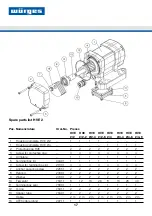
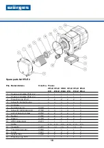
Page 16: ... the spare parts list We only provide warranty for the original spare parts supplied by us We expressly point out that spare parts and accessories that are not original parts supplied by us have not been tested and approved by us Installing and or using such products can therefore cause negative changes to the spe cified design properties and therefore impair active and or passive safety Würges do...

Page 17: ...4 4 4 4 4 4 4 Armature 1 1 1 1 1 1 1 1 5 Terminal box lid 00401 1 1 1 1 1 1 1 1 6 Screw for terminal box lid 21301 4 4 4 4 4 4 4 4 7 Anchor securing screw 22551 2 2 2 2 2 2 2 2 8 Bearing 24301 2 2 2 2 2 2 2 2 9 Washer 27001 2 2 2 2 2 2 2 2 10 Flyweight 75311 8 12 16 26 8 16 26 40 11 Terminal box seal 75801 1 1 1 1 1 1 1 1 12 O ring 75911 2 2 2 2 2 2 2 2 13 Spacer tube 76401 2 2 2 2 2 2 2 2 Cable 2...

Page 18: ... cap 4 4 4 4 4 4 4 Armature 1 1 1 1 1 1 5 Terminal box lid 00401 1 1 1 1 1 1 6 Screw for terminal box lid 21301 4 4 4 4 4 4 7 Anchor securing screw 22551 2 2 2 2 2 2 8 Bearing 24301 2 2 2 2 2 2 9 Washer 27001 2 2 2 2 2 2 10 ATEX cable gland 29711 1 1 1 1 1 1 Cable 2 m 2 m 2 m 2 m 2 m 2 m 12 Flyweight 75311 8 12 16 8 12 16 13 Therminal box seal 75801 1 1 1 1 1 1 14 O ring 75911 2 2 2 2 2 2 15 Space...

Page 19: ...delivered to us carriage paid 10 Disposal and Recycling Würges provides warranty for 1 year begin ning with delivery for all new vibrating motors Warranty expires when the motor is connected wrong or connec ted with wrong voltage the motor fails because of missing or wrong electric protection there were changes made to the motor the motor was damaged during transport the motor was not installed as...

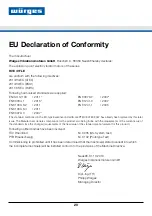
Page 20: ...lready been replaced by this later issue The Manufacturer declares compliance for the product also being in line with the requirements of the current issue of the standard since the changed requirements of the new issue of the standard are not relevant for this product Following notified bodies have been involved TÜV Rheinland Nr 0035 QS System Test PTB Braunschweig Nr 0102 Prototype Text Commissi...

Page 21: ...21 Notes ...

Page 22: ...22 Notes ...

Page 23: ...23 Notes ...

Page 24: ...24 Würges Vibrationsmotoren GmbH Boschstraße 9 D 86356 Neusäß Telephone 49 821 999824 00 Telefax 49 821 999824 10 E Mail info wuerges de Web www wuerges de 10 2019 ...

Reviews: