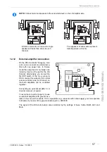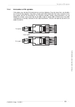
Connecting external speakers in operating mode 2-CHANNEL
PRINCESS – Edition: 17.02.2005
47
FIELD SERVICE MANUAL
11.6
Connecting external speakers in operating mode 2-CHANNEL
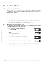
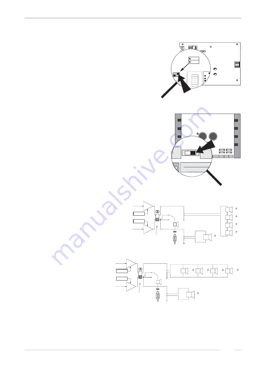
For 2-CHANNEL operation both amplifier switches, the
mode switch and the slide switch S1 on the power am-
plifier board are set to position 2-CHANNEL.
As the following examples show, in the 2-CHANNEL
mode it is possible to connect different loads to each
amplifier output. Take care that the min. impedance is
4
Ω
per channel.
Example 1:
1st room a speaker of 4
Ω
200W, 2nd room 4speaker of
2
Ω
30W connected in series
Example 2:
1st room a speaker of 4
Ω
200W, 2nd room 4speaker of
16
Ω
50W connected in parallel
Low Level
BGM
Mic.-Kit
L
R
Line Out
L
R
Input Tape
L
R
Input CD
Amplifier F91
0039155
BGM Level
R
L
L
R
Clipping
P10
Remote
P10
Remote
P4
1
2
4
1
2
4
Tone
off
on
Treble
Bass
1
2
4
8
16
32
1
2
4
8
16
32
Volume
off
on
R
L
Mode
Input
CD
Stereo
Tape
2-Kanal
R
L
Volume
Mode
Input
CD
Stereo
Tape
2-Kanal
R
S1
S1
P12
mode switch
2-channel / stereo
slide switch S1
in position 2-channel
L
R
2K
monitor
speaker
normal
terminal
screwing terminals
2
30W
2
30W
+
_
+
_
2
30W
2
30W
+
_
+
_
4
200W
+
_
+/- Volume
+/- Balance
stereo
slide switch
L
R
2K
16
50W
16
50W
16
50W
16
50W
+
_
+
_
+
_
+
_
4
200W
+
_
+/- Volume
+/- Balance
monitor
speaker
normal
terminal
screwing
terminals
2-channel /
stereo slide
switch
Summary of Contents for PRINCESS
Page 1: ...R 18 PRINCESS 18 ...
Page 81: ......


