10
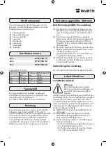
Device elements
Before using the device, the operator must familiar-
ise himself with all device features and the applica-
ble safety instructions.
1
Anti fall guard
2
Safety suspension
3
Locking nut
4
Cable wedge socket
5
Ferrule
6
Cable clamp
7
Rubber buffer
8
Spring catch
Device data
Art.
0715 938 12
Art.
0715 938 23
Art.
0715 938 36
Type series F2, F3, F6
Standard Load
(kg)
Cable extension
(m)
Dead load
(g)
F2
0,5-2,0 2,5
750
F3
1,5-3,0 2,5
800
F6
3,0-5,5 2,5
900
Type plate
The type plate is fixed on the housing.
there, you will find data on the type series and the
admissible load range.
The type plate includes also the CE sign.
Introduction
These operating instructions have been compiled
for the devices of the following type series: F2, F3
and F6
The basic structure is identical, however, each series
type is designed for a specific load range.
These operating instruction provides information for
installation by adaequately trained specialist person-
nel and information concerning proper operation by
specially instructed personnel.
Proper application
Proper use
The device is exclusively designed for keep-
ing hand-held tools, such as drilling machines,
compressed air screwdrivers etc.
Another or additional use shall be deemed to
be improper use! The manufacturer / supplier
will not accept any responsibility for damages
resulting from any improper use. Associated risks
shall be borne by the user alone.
If the device is applied in a field not covered
by the proper use decribed above, any claim
of guarantee shall be void unless the written
approval of
Adolf Würth GmbH & Co. KG has been ob-
tained beforehand.
Spring balancers may only be operatied,
installed, maintained, and repaired by specially
trained personnel.
Improper use
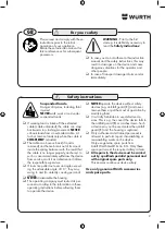
The device may not be used as crane.
Start-up
Installation (fig.II)
Important
The device may only be put into
operation by authorized and trained
personnel.
Versions with plastic housings may not
be installed in the immediate vicinity of hot-air blow-
ers. The suspension structure to which the device and
the antifall guard (
1
) is to be fitted must be designed
with a safety factor of at least 5 (5 x [dead weight
of the spring ba maximum admissible load]).
Install the device using the safety suspension (
2
).
Ensure that the device cannot slip out of the
safety suspension (
2
)
⇒
tighten locking nut (
3
).
When fasteing the antifall guard (
1
) to the
suspension structure make sure that:
• The range of movement of the device is not
restricted.
• The falling distance does not exceed 100 mm!
Summary of Contents for 0715 938 12
Page 3: ...I 363 45 166 5 46 26 5 4 5 78 117 133...
Page 4: ...II III IV 1 2 3 4 5 7 6 min 100 mm 8...
Page 49: ...49 GR 10 1 1 1 Adolf W rth GmbH Co KG W rth...
Page 51: ...51 III F2 F3 F6 2 5m 6 7 IV Plus 8 4 mm 8 X F2 6 4 F3 5 2 F6 3 4 X Minus...
Page 81: ...81 BG 10 1 1 1 Adolf W rth GmbH Co KG W rth...
Page 83: ...83 III F2 F3 F6 2 5m 6 7 IV 8 4 mm 8 X F2 6 4 F3 5 2 F6 3 4 X...
Page 97: ...97 RU 10 1 1 1 Adolf W rth GmbH Co KG W rth...
Page 99: ...99 III F2 F3 F6 2 5m 6 7 IV 8 4 8 X F2 6 4 F3 5 2 F6 3 4 X...
Page 101: ......
Page 102: ......
Page 103: ......

