15
■
Press the trigger lever
[9]
once to remove re
-
sidual wax from the hollow space probe.
■
Close the nozzle regulator
[8]
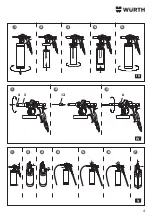
(Fig. 1/V).
■
Close the air regulator
[2]
(Fig. 2/V).
■
Close the air vent regulator
[3]
by turning up
-
wards in an anticlockwise direction (Fig. 3/V).
■
Connect the compressed air supply and com
-
pletely open the air
supply
regulator
[11]
.
■
Press the trigger lever
[9]
up to the first step
to check whether the air vent regulator
[3]
is
closed. If the valve is closed, no air escapes
(Fig. 4/V).
■
Open the air regulator
[2]
by half a turn.
■
Press the trigger lever
[9]
. Air must flow out of
the hollow space probe.
■
Slowly open the air regulator
[8]
(starting with at
least one full turn) and keep the trigger lever
[9]
pressed until hollow space wax flows out of the
probe (Fig. 5/V).
■
Adjust the density of the spray mist using the air
regulator
[2]
(Fig. 6/V).
Note
Do not open the air supply too far,
otherwise the air can close the hollow
space probe and stop the product flow.
■
Set the product quantity with the regulator
[8]
and air supply with the air regulator
[2]
so that
the optimum compromise is achieved between
product quantity and density of the spray mist
(Fig. 7/V).
Conventional products
Setting the product quantity
■
Turn the nozzle regulator
[8]
:
• Clockwise: Product quantity reduces.
• Anticlockwise: Product quantity increases.
Note
Do not exceed the pre-setting. Other
-
wise there is a risk that the regulator
will eject forcefully due to the spring
force.
Setting product atomisation
■
Turn air regulator
[2]
:
—
Clockwise: The air passage reduces and atomi
-
sation reduces (becomes coarser).
—
Anticlockwise: The air passage increases and
atomisation increases (becomes finer).
With open product
■
Pour product into the detachable tank directly.
Note
Fill the bottle with no more than one
litre.
■
Position the detachable tank and tighten in a
clockwise direction (Fig. 4/III and 5/III).
■
If necessary, Set hollow space sealing (see
hollow space sealing chapter).
■
Set the relevant product (see conventional or
water-based product chapter).
■
Point the device at the surface to be sprayed
from a distance of 10 to 30 cm.
■
Press the trigger lever
[9]
.
3
The device sprays.
■
After use, disconnect the device from the
compressed air supply and clean (see section
Maintenance / Care).
Hollow space sealing
Fitting of the hollow space probes
(Fig.
IV)
■
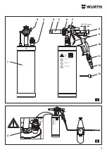
Screws the nozzle cap
[4]
anticlockwise and
remove from the nozzle holder
[5]
.
■
Select the appropriate hollow space probe
[13]
and screw onto the nozzle holder
[5]
in a clock
-
wise direction.
Note
Unscrew the union nut
[6]
and instead
screw the hollow space probe on
to the nozzle holder in a clockwise
direction so that the hollow space
probe is securely screwed on to the
nozzle holder. Then tighten the union
nut again.
Setting hollow space sealing
(hollow space wax) (Fig. V)
Attention!
Risk of property damage
■
The pressure can also cause the product to
flow out and cause the device to stick strongly
together.
¾
Never completely shut the air regulator
[2]
during use.
Summary of Contents for 0891 110 640
Page 3: ...10 12 mm AIR EXIT 3 II I 8 7 3 3 1 2 10 11 12 9 4 5 6 13...
Page 4: ...4 5 5 6 7 4 4 3 3 3 2 2 2 1 1 1 III IV V 4 5 6 13...
Page 82: ...82 GR W rth 3 3 1...
Page 83: ...83 18 16 8 bar...
Page 86: ...86 2 2 11 11 3 4 bar 4 bar 8 2 8 10 12 mm 3 3 2 2 3 2 2 2 3 2 11...
Page 87: ...87 9 11 11 2 45 3...
Page 138: ...138 BG W rth 3 3 1...
Page 139: ...139 18 16 8 bar...
Page 142: ...142 2 2 11 11 3 4 bar 4 bar 8 2 8 10 12 mm 3 3 2 2 3 2 2 2 3 2 11...
Page 143: ...143 9 11 11 2 45 3...
Page 166: ...166 RU W rth 3 3 1...
Page 167: ...167 18 16 8...
Page 170: ...170 2 2 11 11 3 4 4 8 2 8 10 12 3 3 2 2 3 2 2 2 3 2 11...
Page 171: ...171 9 11 11 2 45 3...
Page 173: ...173...
Page 174: ...174...
Page 175: ...175...


