31
support is performed by placing the assembly feet on the screws
located on the cylinder head).
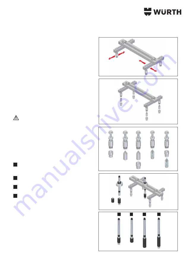
• Position the crosshead already assembled with the sliding
groups in correspondence of the screws on the head (fig. 10).
• In the case of large differences in height, it is possible to use the
support foot extension group 1952 003 514 or the extension
for the adjustable foot 1952 003 515
(fig. 11).
• Here at the side are shown the configurations which are possible
using the feet 1952 003 515 and 1952 003 514 according to
the type of screws (hexagonal or cylindrical head with hexagon
socket) located on the engine head (fig. 12).
• Place the washer with bearing 1952 003 519 on the crosshead
1952 003 511.
• Tighten the screw 1952 003 518 and adjust its height using the
nut 1952 003 525 with wrench CH.30 (fig. 13).
For problems of height select the type of extension 1952 003
527 or 1952 003 528 depending on the type of adapter
used.
• Here at the side are shown the configurations which are possible
using the extension 1952 003 527 or 1952 003 528 (fig. 14).
Configurations
:
1
For adapters 1952 003 520 - 1952 003 521 - 1952 003
522 - 1952 003 523 - 1952 003 524
2
For adapters 1952 003 526
3
For adapters 1952 003 526 with deeper injectors.
4
For adapters 1952 003 520 - 1952 003 521 - 1952 003
522 - 1952 003 523 - 1952 003 524 with deeper injectors.
• Tighten the screw 1952 003 518 (or extension if used) to the
adapter already fastened to the injector and make sure that the
plane of the crosshead 1952 003 511 is perpendicular to the
axis of the screw.
• By tightening the nut 1952 003 525 the washer with bearing
1952 003 519 must rest perfectly on the crosshead 1952 003
511, otherwise adjust the support feet on the cylinder head
screws.
• The fine adjustment of height is performed by rotating the
threaded part of the support foot 1952 003 513.
11
12
13
1952 003 527
1952 003 528
14
4
1
2
3
10


