35
DEU
ENG
NDL
FRA
ITA
ESP
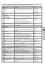
4.5.2 Configuration with room control unit Wireless Display (continued)
No.
Parameters
Description
Unit
040 External sensor connected to
the RBG
Logging on an additional sensor for the registration of the
floor temperature (FBH), the room temperature or the dew
point
no sensor=0
Dew point sen.=1
Temp FBH=2
Temp room=3
060 Correction of actual value
registration
Registration of the actual temperature with a correction factor -2.0...+2.0 K
in 0.1 increments
110 Control direction
switching outputs
Switchover of NC and NO actuators (only globally)
NC=0 / NO=1
115 Use as setback input
Change-over between use of the ECO input for setback or
holiday function of the room control unit.
The holiday function cannot be activated any longer via the
room control unit if this parameter has been set to 1.
ECO=0
Holiday=1
120 Unit of temperature display
Toggle function of the display between degree Celsius and
degree Fahrenheit
°C=0
°F=1
Pump configuration
130 Pump output
Use the control of a local recirculation pump (in the heating
circuit distributor) or a global recirculation pump (heating
installation).
local=0
global=1
131 Pump type
Selection of the used pump: Conventional Pump (KP) / High
efficiency Pump (HP)
CP=0
HP=1
132 Pump line-up time
Time elapsing from the moment of the command from a
switching output until the pump is actually switched on.
[min]
133 Pump follow-up time
Time elapsing from the moment of switching off the switching
outputs until the pump is actually switched off.
[min]
134 Control direction switching
output
The control direction can be inverted if the pump relay is used
as control output
normal=0
inverted=1
135 Minimum running time
The minimum running time indicates how long the HP must run
until it may be switched off again.
[min]
136 Minimum standstill time
High efficiency pump: The pump may only be switched off if
a minimum standstill time can be ensured.
[min]
Configuration of change-over functionality / boiler relay
140 Function of relay boiler / CO
output
Selection whether the switching output shall serve for control-
ling a pump relay, or as CO pilot
Boiler=0
CO pilot=1
141 Line-up time
Boiler relay line-up time for conventional pump
[min]
142 Follow-up time
Boiler relay follow-up time for conventional pump
[min]
143 Control direction switching
outputs
The relay function can be inverted if used as a control output. normal=0
inverted=1
160 Antifreeze protection
Activation of control outputs for T
actual
<x °C
Deactivated=0
Activated=1
161 Antifreeze temperature
Antifreeze function limit value
[°C]
170 Smart Start
Learning-in of the temperature behaviour of the individual
heating zones
Deactivated=0
Activated=1


