17
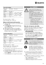
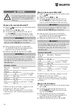
Resistance measurement
■
Set the selector switch measurement range to
Ω
.
■
Connect the black measuring lead to the
COM
socket
[5]
and the red measuring lead to
the
V
Ω
A
socket.
■
Connect the measuring leads to the test object.
3
The multimeter automatically searches for the
most favourable measurement range.
■
Read the measurement result from the dis
-
play
[1]
.
Resistance
Measuring
range
Resolution
Accuracy
200 Ω
0.1 Ω overvolt
-
age protection:
250 V AC / DC
± 1 % + 5 digits
2 kΩ
0.001 kΩ
± 1 % + 5 digits
20 kΩ
0.01 kΩ
200 kΩ
0.1 kΩ
2 MΩ
0.001 MΩ
20 MΩ
0.01 mΩ
± 1.8 % + 5
digits
Measuring voltage: 0.25 V.
Overvoltage protection: 600 V AC / DC < 30 s.
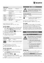
Diode test
■
Set the selector switch measurement range to
Ω
. Connect the black measuring lead to the
COM
socket
[5]
and the red measuring lead to the
right socket.
■
Set
M
button
[8]
to
. Connect the measuring
leads to the test object.
■
Red measuring lead = anode,
■
Black measuring lead = cathode.
3
The reverse voltage is displayed.
Diode test
Measuring
range
Resolu-
tion
Accuracy
0.001 V
Indicates the reverse
voltage
■
Test current: approx. 0.6 mA,
Reverse voltage: approx. 1.5 V.
■
Overvoltage protection: 600 V AC / DC < 30 s.
Continuity test
■
Set the selector switch measurement range to
Ω
.
■
Connect the black measuring lead to the
COM
socket
[5]
and the red measuring lead to the
right socket.
■
Set
M
button
[8]
to
.
■
Connect the measuring leads to the circuit being
tested.
3
For electric paths that are continuous, i.e. resis-
tance less than 50 Ω, a beep is emitted.
■
Read the measurement result from the dis
-
play
[1]
.
DANGER!
Check for a zero-volts condition and
that capacitors in the measuring circuit
are discharged
Continuity test
Measuring
range
Function
The integrated buzzer signals conti
-
nuity up to 50 Ω
■
Measurement circuit voltage: approx. 0.5 V.
■
Overvoltage protection: 600 V AC / DC < 30 s.
True RMS
Where non-sinusoidal waveforms are measured,
and the True RMS function is used, then the resultant
measurement errors are smaller than those occurring
when using conventional measurement methods.
Sinusoidal and non-sinusoidal signals can be mea
-
sured exactly using the True RMS function.


