5
GB F E D I N FIN
4
1.4 Laser overview
See inside front cover for photos of the laser and keypad corre-
sponding to these callouts. See separate descriptions of motorized
mount, remote control, and detectors.
1. Rotating head
2. Aluminum head protection with axes indications
3. Plumb or square laser beam aperture
4. Rotating laser beam aperture
5. Collar to switch between point & chalk line
6. Index marks for alignment and 90°
7. Motorized wall or floor mount
8. Batteries
9. Jack for battery charger
10. 5/8 - 11 tripod mount for horizontal set-up
11. 5/8 - 11 tripod mount for vertical set-up
12. Sensors for remote control signal
1.5 Keypad overview
13. Move left: scan or vertical alignment/
Move calibration beam up
14. Move right: scan or vertical alignment/
Move calibration beam down
15. Decrease rotation speed or scan angle/ Move stationary point
or chalk line left /
Save calibration
16. Increase rotation speed or scan angle/ Move stationary point
or chalk line right/
Change calibration axis
17. On / Off
18. H.I. Alert
19. Automatic / Manual mode
20. Low battery LED /
X axis calibration LED
21. H.I. Alert LED /
Y axis calibration LED
22. Manual mode LED /
Z axis calibration LED
Italics indicate keys and LEDs used in calibration mode.
1.3 Specifications
Recommended use
1,000 ft. (300 m) diameter
Leveling accuracy
± 3/32” at 100 ft.
(± 0.0075% ± 7,5 mm at 100 m)
Self-leveling
Horizontal and vertical
Leveling range
± 10%
Rotation speed
0, 90, 150, 300, 450, 600 rpm
Scanning angle
Variable, from 2 to 36°
Laser diode
Visible 635 nm; <5mW Class 3R
Power
2 D size (LR20) alkaline batteries
or rechargeable batteries
Battery life
160 hours with alkaline batteries
40 hours with rechargeable batteries.
Charging time
15 hours
Remote detection
100 ft. (30 m) / 180°
Environmental
Weatherproof
(rain and dust proof – IP64)
Weight
3 lbs. (1.5 kg)
Size
7.75’’x 8’’x 5.5’’ (19.5 x 21 x 14 cm)
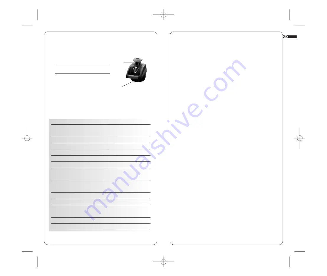
B.
Aperture label
AVOID EXPOSURE. LASER LIGHT
IS EMITTED FROM THIS APERTURE
B
A
WLA08-pg1-124 22/05/08 19:53 Page 4


