


• Connect the
pin to the host controller to leave power saving modes,
like the sleep mode.
• Connect the
pin to the host controller to set the module into boot mode to
enable firmware updates via radio.
• Connect the
pin to the host controller to switch between command and
peripheral only mode.
7. (Optional) Status indication
Connect the
and
pins to the host controller to allow easy indica-
tion of the status.
8. (Optional) Flash and debug interface
It is recommended to additionally have the pins
and
accessible in
order to support a fail-safe firmware update. A standard socket on the customer’s PCB
for connecting a flash adapter can be useful for debugging purposes (e.g. a JTAG 2*10
pin header with 2.54mm pin-to-pin distance).
If the module has to be connected to a PC, a converter (TTL to RS-232 or TTL to USB) has
to be used. See chapter
for details on all pins. Please refer to the Proteus-III-EV schemes
for a reference design.
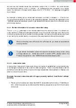
The logic level of the module is based on 3V. A 5V logic level must not be
connected directly to the module.
Proteus-III reference manual version 1.3
© August 2020
www.we-online.com/wireless-connectivity
24


