


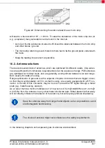


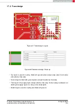


Figure 22: Dimensioning the antenna feed line as micro strip
will lead to a trace width of W
∼
1.9 mm. To ease the calculation of the micro strip line (or
e.g. a coplanar) many calculators can be found in the internet.
• As rule of thumb a distance of about 3×W should be observed between the micro strip
and other traces / ground.
• The micro strip refers to ground, therefore there has to be the ground plane underneath
the trace.
• Keep the feeding line as short as possible.
16.3. Antenna solutions
There exist several kinds of antennas, which are optimized for different needs. Chip anten-
nas are optimized for minimal size requirements but at the expense of range, PCB antennas
are optimized for minimal costs, and are generally a compromise between size and range.
Both usually fit inside a housing.
Range optimization in general is at the expense of space. Antennas that are bigger in size,
so that they would probably not fit in a small housing, are usually equipped with a RF con-
nector. A benefit of this connector may be to use it to lead the RF signal through a metal
plate (e.g. metal housing, cabinet).
As a rule of thumb a minimum distance of
λ
/10 (which is 3.5 cm @ 868 MHz and 1.2 cm @
2.44 GHz) from the antenna to any other metal should be kept. Metal placed further away
will not directly influence the behavior of the antenna, but will anyway produce shadowing.
Keep the antenna away from large metal objects as far as possible to avoid
electromagnetic field blocking.
The choice of antenna might have influence on the safety requirements.
In the following chapters, some special types of antenna are described.
Proteus-III reference manual version 1.3
© August 2020
www.we-online.com/wireless-connectivity
187