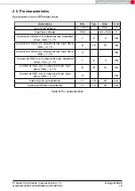


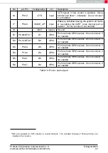


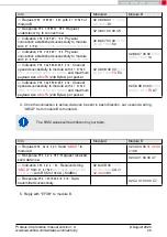

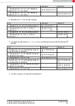

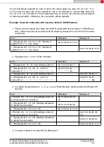


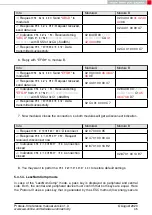
5.1. State indication using the LED pins
The pins
and
of the Proteus-III can be used to determine the module state.
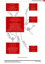
The states described in Figure
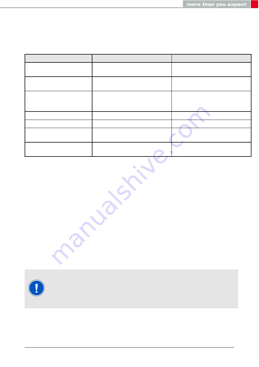
result in the following pin behavior. The pins on the Proteus-
III are active high.
State
ACTION_IDLE
Blinking (On for 200 ms, Off for
2800 ms)
Off
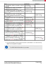
ACTION_SCANNING
Blinking (On for 1000 ms, Off for
1000 ms)
Off
ACTION_CONNECTED
On
Off, On (as soon as the channel
was opened successfully, see
ACTION_SLEEP
Off
Off
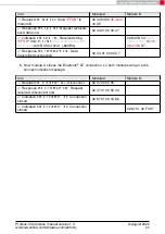
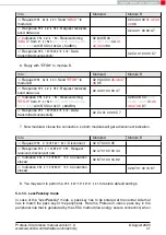
ACTION_DTM
Off
Off
BOOTLOADER
waiting for
connection
On
Off
BOOTLOADER
connected,
firmware update running
Off
On
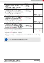
Table 11: LED behavior of the Proteus-III
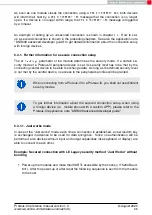
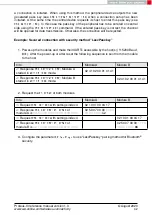
5.2. Sleep mode
Especially for battery-powered devices the
ACTION_SLEEP
mode (system-off mode) supports
very low power consumption (<1µA). It can be entered by sending the command
to the module. As response, the module will send a
and then enter the
ACTION_SLEEP
mode.
In
ACTION_SLEEP
mode the UART is disabled. Thus the module will not receive or transmit
any data. To prevent leakage current, the host shall not pull the
to LOW level (as the
module has an internal pull-up resistor enabled on this pin).
To leave the
ACTION_SLEEP
mode and enter
ACTION_IDLE
state again, the module has to be
woken up by applying a low signal to the
pin for at least 5 ms before releasing the
signal back to high. The module then restarts completely, so that all volatile settings are set
to default. A
will be send when the module is ready for operation again.
Please note that the
pin has a second function.
If the mod-
ule is not in
ACTION_SLEEP
mode and the UART was disabled using the
, the UART can be re-enabled by applying falling edge,
holding the line low for at least 10ms before applying a rising edge and
holding it high for at least 10ms. In this case the module answers with a
message.
Proteus-III reference manual version 1.3
© August 2020
www.we-online.com/wireless-connectivity
33


