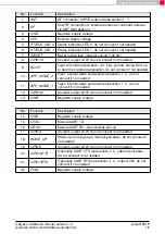
No
Function
Description
1
RF connection to PCB antenna (see section
2
50
Ω
RF connection to external antenna or onboard antenna
via ANT (see section
3
Negative supply voltage
4
Positive supply voltage
5
Status indication LED 0, do not connect if not needed
6
Status indication LED 1, do not connect if not needed
7
Reset (active low), internal pull-up (100 k
Ω
)
8
Unused, output LOW, do not connect if not needed
9
Input with internal pull-down (2.7 k
Ω
), pull low during start-up
to boot the standard application, do not connect if not needed
10
Input, internal weak pull-down (see section
), do not
connect if not needed
11
Input, internal weak pull-down (see section
), do not
connect if not needed
12
Unused, output LOW, do not connect if not needed
13
Negative supply voltage
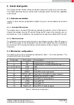
No
Function
Description
14
Negative supply voltage
15
Module UART TX
16
Module UART RX, internal weak pull-up
17
Unused, output LOW, do not connect if not needed
18
Wake-up on rising edge, internal pull-down, do not connect if
not needed
19
Unused, output LOW, do not connect if not needed
20
Optionally UART CTS (see section
), internal pull-down,
do not connect if not needed
21
Optionally UART RTS (see section
), output LOW, do not
connect if not needed
22
Negative supply voltage
Calypso reference manual version 1.2
© April 2019
www.we-online.com/wireless-connectivity
18

