background image

17

US/CAN/MEX: +1-518-289-1294     Toll Free Technical Support: +1-844-280-WYRE (9973)

QUICKSYNC SETTING

14.     EDID Management -

           About EDID

EDID (Extended Display Identification Data) is 

data generated from each display in the system to 

communicate the capabilities of the device (720p, 2ch 

Audio, 1080p, 7.1ch Audio). 

For communication between devices to be made, 

and successful connection achieved, devices must 

both request and send the required information.  For 

example, a display will communicate 1080p capability 

with 2ch audio, which the source device will accept and 

output the correct format for the display.  Problems can 

arise when different types of devices such as displays, 

sources and amplifiers are used within a system, making 

communication between them that much more difficult; 

sometimes resulting in connection problems.

In such instances EDID needs to be streamlined or guided 

for all devices to work together, with equipment such as 

the MX-PP-POH and RX-70-IR-POH display receivers  

perfectly placed to handle this process as communication 

between display and source is the most important in the 

system. The effective control and management of EDID is 

essential for the success of any integration, with this being 

achieved in most cases using the default setting on the 

matrix and receivers.

15.     Before EDID 

          Adjustments

Communication between sink, matrix and source devices 

should be automatically negotiated with the EDID DIP 

switch set to the default Normal Output (OFF) position.  

However, should device communication or compatibility 

issues be encountered during installation, please refer to 

the EDID DIP settings below.

If the maximum capabilities of the display are known, for 

example 1080p 3D with 2ch stereo audio, the DIP switch 

setting should be adjusted manually for matching EDID to 

be sent to the matrix.

If the specification of the display is not known, simply 

copy the EDID from the display to matrix through the 

HDMI connection by setting all switches to the EDID Copy 

or Force Output (ON) positions and power cycling the 

matrix for the DIP setting to become active.

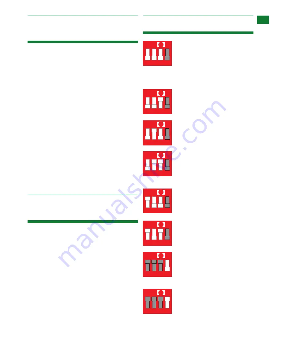
16.     EDID Presets

Copy EDID from the HDMI sink 
device to the currently selected 
input port

                            For example, when output-3 select 
input-1, the EDID of output-3 will be copied to input-1. 
(An HDMI output takes precedence over a UTP output. If 
a copy fails, the EDID will remain the same.)

1 2 3 4

ON

                            The matrix will use 3D compatible 
                            1080p-stereo EDID when the DIP 
                            switch is in this setting.

1080p 3D stereo

1 2 3 4

ON

                            The matrix will use 1080p-stereo EDID 
                            when the DIP switch is in this setting.

1080p stereo

1 2 3 4

ON

                            The matrix will use 1080i-stereo EDID  
                            when the DIP switch is in this setting. 
                            This setting is useful if using an older 
model TV or if the screen does not support full 1080p.

1080i stereo

1 2 3 4

ON

                            The matrix will use 3D compatible 
                            1080p-5.1 EDID when the DIP switch is  
                            in this setting.

1080p 5.1

1 2 3 4

ON

                            The matrix will use 3D compatible 
                            1080p-7.1 EDID when the DIP switch is 
                            in this setting.

1080p 7.1

1 2 3 4

ON

Normal Output

                            This setting instructs the matrix to
                            check the hotplug voltage and EDID of
                            the sink device prior to outputing the 
HDMI signal.

1 2 3 4

ON

1 2 3 4

ON

Force Output

                            This setting instructs the matrix to
                            continually output HDMI signals 
                            regardless of hotplug voltage being 
detected from the sink device.

Summary of Contents for MX-1616-PP-POH

Page 1: ...Fixed Pro Plus chassis featuring PoH HDBaseT out mirrored HDMI out HDMI in IR input transmission card Modular Pro Plus chassis with selection of customisable analogue and digital PoH transmission card...

Page 2: ...selection from a range of multi format digital and analogue transmission cards that enable distribution and control to be tailored to the specifics of the project like never before Using our Virtual...

Page 3: ...yrestorm com US 866 677 0053 EU 44 0 1793 230 343 FEATURES AND SAFETY PREC Quick and easy installation set up in seconds straight out of the box Simplified ports Input HDMI Output integrated RJ45 conn...

Page 4: ...32 to 95 F Operating Humidity Range 5 to 90 RH no condensation Output Bandwidth Signalling Rate 6 75Gbps Input Video Signal 0 5 1 0 volts p p Input DDC Signal 5 volts p p TTL Maximum Single Link Rang...

Page 5: ...ports mirrors HDBaseT output Earth ground point HDMI input ports 7 6 LAN port RS485 port 7 6 8 8 9 9 12 12 13 13 14 14 IR extension port should front panel IR receiving sensor be obstructed or matrix...

Page 6: ...230ft HDBaseT transmission for Video Audio Control Power with IR in for control signals to be sent to the sink device HDBaseT out Audio breakout HDMI in IR in Similar to the TX POH 010 card this vari...

Page 7: ...ng an HDBaseT transmitter with received signals then routed by the matrix as with any local source Control of source device cannot be routed internally through the matrix an IR loop port is included o...

Page 8: ...25w d class amp 25w d class amp rx 70 poh HD Audio Video PERSONAL AUDIO DEVICE Key cat 5e 6 70m 230ft VGA dvi hdmi rs232 ir tx ir rx sub pre out Line Level Audio rx 70 poh HD Audio Video Games Consol...

Page 9: ...ONAL AUDIO DEVICE cat 5e 6 70m 230ft VGA dvi hdmi rs232 ir tx ir rx sub pre out Line Level Audio Audio return channel from tv Slot 1 TX POH 010 Slot 2 TX POH 020 Slot 3 TX POH 040 Slot 4 TX POH 030 Sl...

Page 10: ...ed using Cat5e as standard we suggest using Cat6 as the preferred cable due to its improved transmission capabilities Ensure both RJ45 connectors are pushed securely into each port and supported by th...

Page 11: ...R TX or RX eyes is not affecting the infrared signal The WyreStorm MX PP POH is designed with ease of set up and use in mind Basic switching of source inputs to output displays can be achieved via the...

Page 12: ...ures an intuitive IR Call Back system of control through which the matrix is able to distinguish where the remote handset is being used to change INPUTS and OUTPUTS and is able to switch accordingly d...

Page 13: ...3 1 2 3 4 4 IR Path IR Path IR Path UTP Out 1 UTP Out 2 UTP Out 3 UTP Out 4 UTP Out 5 UTP Out 6 UTP Out 7 UTP Out 8 1 2 3 4 1 1 2 3 4 2 1 2 3 4 3 1 2 3 4 4 01 02 01 At Matrix end Insert the 3 5mm jack...

Page 14: ...ried along the single Cat5e 6 7 cable Insert 3 5mm jacks of IR receivers into RX ports making sure the receivers themselves are placed in clear view at the to receive an infrared signal from the remot...

Page 15: ...s requiring even greater distribution a customisable modular MX PP POH solution featuring HDMI source loop HDMI passthru offers the opportunity to cascade up to 7 matrices for a total distribution to...

Page 16: ...PP POH matrices to control compatible display receiver devices routed serial commands to the receiver device RX 70 POH or AMP 001 010 via the matrix should be sent in the following command string For...

Page 17: ...ing installation please refer to the EDID DIP settings below If the maximum capabilities of the display are known for example 1080p 3D with 2ch stereo audio the DIP switch setting should be adjusted m...

Page 18: ...equirements and is well within the maximum transmission distance of the signal NOTE If approaching the limits of the transmission capabilities transmission should be extended by using another extender...

Page 19: ...etween sources displays and or AV receiver settings 1 Have specific speaker sets or zones been enabled Some AV receivers allow individual speaker selections assigned to specific zones in the set up so...

Page 20: ...he problem it is likely that electromagnetic interference damage to the cable somewhere along the run is causing the IR signal to drop out Investigate and remove EM interference from the run or replac...

Page 21: ...lly handle 1080p signals including those at increased colour depths and or increased refresh rates from the Source High Speed cables are also able to accommodate higher resolution displays such as WQX...

Page 22: ...e as well as the price paid for the product The customer will be charged for the repair of any unit received unless such information is provided 22 Warranty Should you feel your product does not funct...

Page 23: ...limited warranty are not the responsibility of the warrantor and should be considered the responsibility of the individual 24 Disclaimer WYRESTORM PUBLICATION DISCLAIMER The material contained in this...

Page 24: ...ROW 44 0 1793 230 343 INSTALLATION REFERENCE LOG 1 2 3 4 5 6 7 8 9 10 12 13 14 15 16 output Output number on Matrix Cable Number Output Location Display Details Display Resulution Audio Settings 25 I...

Page 25: ...e Technical Support 1 844 280 WYRE 9973 INSTALLATION REFERENCE LOG 1 2 3 4 5 6 7 8 9 10 12 13 14 15 16 output Output number on Matrix Cable Number Output Location Display Details Display Resulution Au...

Page 26: ...A Office Unit 22 Ergo Business Park Swindon Wiltshire SN3 3JW UK Tel 44 0 1793 230 343 WyreStorm Technical Support US 1 844 280 WYRE 9973 UK 44 0 1793 230 343 Email support wyrestorm com WyreStorm Tec...

Reviews: