background image

Summary of Contents for WY-50

Page 1: ...WY 50 Display Terminal Maintenance Manual WYSE I I I I ...

Page 2: ...WY 50 DISPLAY TERMINAL MAINTENANCE MANUAL WYSE NO 88 021 01 ...

Page 3: ... Wyse Technology ADM 3l is a trademark of Lear Seigler Data Products Division TeleVideo 910 920 925 are registered trademarks of TeleVideo Systems Inc ADDS Viewpoint is a trademark of Applied Digital Data Systems Inc Hazeltine 1500 is a trademark of Hazeltine Corp COPYRIGHT NOTICE Copyright 1984 Wyse Technology All Rights Reserved Worldwide No part of this publication may be reproduced without the...

Page 4: ...internal phosphor of the CRT cathode ray tube is toxic Wear safety goggles and rubber gloves whenever the CRT is handled If the tube breaks exposing skin or eyes to the phosphor immed iately rinse the affected area with cold water and consult a physician FCC WARRING This equipment generates uses and can radiate radio frequency energy and if not installed and used in accordance with the instruction...

Page 5: ...iv ...

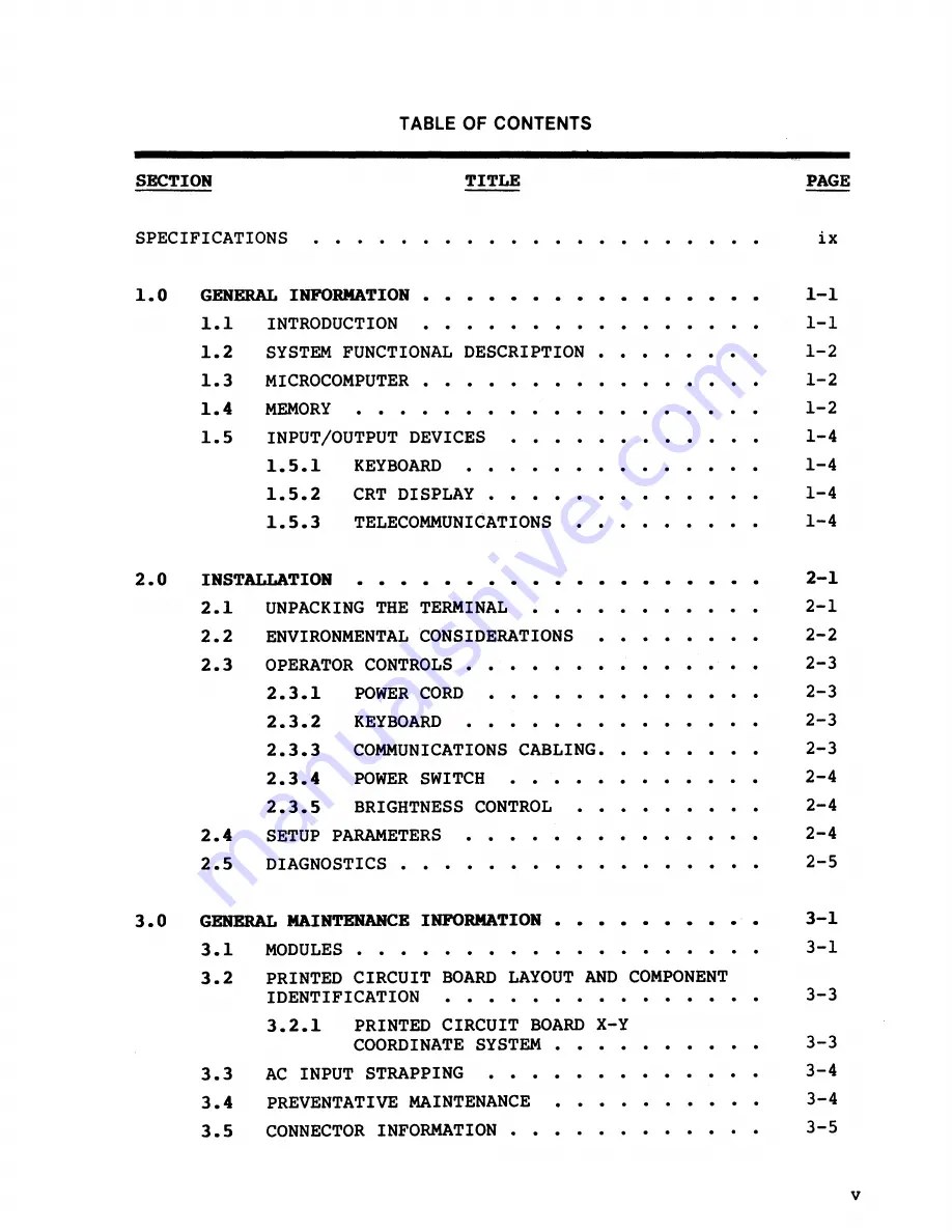
Page 6: ...HE TERMINAL 2 2 ENVIRONMENTAL CONSIDERATIONS 2 3 OPERATOR CONTROLS 2 3 1 POWER CORD 2 3 2 KEYBOARD 2 3 3 COMMUNICATIONS CABLING 2 3 4 2 3 5 POWER SWITCH 2 4 2 5 BRIGHTNESS CONTROL SETUP PARAMETERS DIAGNOSTICS GENERAL MAINTENANCE INFORMATION 2 1 2 1 2 2 2 3 2 3 2 3 2 3 2 4 2 4 2 4 2 5 3 1 3 1 MODULES 3 1 3 2 PRINTED CIRCUIT BOARD LAYOUT AND COMPONENT IDENTIFICATION 3 3 3 2 1 PRINTED CIRCUIT BOARD X...

Page 7: ...ER 4 5 9 ATTRIBUTE CONTROL 4 5 10 CHARACTER GENERATOR 4 5 11 ROW BUFFER DIAGNOSTIC REGISTER 4 5 12 VIDEO SHIFT REGISTER 4 6 RASTER SCAN TERMINOLOGY 5 0 MAIRTENARCE INSTROCTIONS 5 1 MODULE REPLACEMENT 5 2 5 3 5 4 5 5 5 6 5 7 KEYBOARD REPLACEMENT MONITOR POWER SUPPLY REPLACEMENT MONITOR POWER SUPPLY PC CARD REPLACEMENT BRIGHTNESS POTENTIOMETER REPLACEMENT AC POWER SWITCH REPLACEMENT MICROCOMPUTER PC...

Page 8: ...EYBOARD 6 2 4 MONITOR 6 2 4 1 VERTICAL HOLD HEIGHT VERTICAL LINEARITY FOCUS WIDTH 6 2 4 2 6 2 4 3 6 2 4 4 6 2 4 5 6 2 4 6 6 2 4 7 DISPLAY CENTERING DISPLAY LEVELING KEYBOARD CABLE REPLACEMENT 6 1 6 3 6 3 6 3 6 4 6 4 6 4 6 5 6 5 6 5 6 6 6 6 7 0 PERFORMANCE TESTS AND TROUBLESBOO rING PLOW CHART 7 1 7 1 POWER ON SELF TEST 7 1 7 2 DIAGNOSTIC SELF TEST 7 2 7 3 TROUBLESHOOTING FLOW CHART 7 2 vii ...

Page 9: ... MICROCOMPUTER PCB AC INPUT STRAP LOCATIONS MONITOR POWER SUPPLY MICROCOMPUTER PCB BLOCK DIAGRAM MONITOR POWER SUPPLY BLOCK DIAGRAM HORIZONTAL OSCILLATOR TIMING VERTICAL TIMING KEYBOARD BLOCK DIAGRAM ORIENTATION VIEW OF TERMINAL AND COMPONENT NAME MONITOR POWER SUPPLY DISPLAY CENTERING TCOM TEST PLUG TROUBLESHOOTING FLOW CHART TABLES TABLE TITLE ERROR MESSAGE DEFINITION PAGE 1 1 1 3 1 5 2 1 2 2 2 ...

Page 10: ...egree tilt and 270 degree swivel 24 rows x 80 or 132 columns user selectable plus 2 rows for terminal status and function key indentifi cation 80 column 7 x 13 matrix in 10 x 13 cell l32 column 7 x 13 matrix in 9 x 13 cell 128 ASCII upper lower case including 32 control codes and line drawing graphics US American UK British French German Danish Spanish Normal dim blink blank reverse underscore and...

Page 11: ...tional half or full duplex user selectable Can be specified inde pendently for each interface 7 or 8 data bits 1 or 2 stop bits odd even mark or no parity user selectable XON XOFF DTR both or none user selectable Left right up down home tab back tab line feed direct X Y addressing Editing Functions Erase memory erase to end of line field erase to end of screen insert and delete line character Form...

Page 12: ...ional wattage Nonvolatile memory permits soft setup from keyboard for data communications parameters operating modes function key sequences etc WY 100 ADM 3l TeleVideo 910 920 925 ADDS Viewpoint Hazeltine 1500 320 to l130 F 00 to 450 C 400 to 1400 F 400 to 600 C 10 to 90 non condensing Sea level to 15 000 ft 90 to 130 VAC 60 Hz 5 200 to 240 VAC 50 Hz 5 45 watts xi ...

Page 13: ...xii ...

Page 14: ...ins two independent telecommunication interfaces Peripherals such as a hard copy printer connect to the terminal via interface con nectors on the rear panel All the component parts are organized around and controlled by the microcomputer The microcomputer controls all internal data manipulation and processing functions Figure 1 1 is a simplified block diagram of the WY SO r l I EXTERNAL 114 I PRIN...

Page 15: ...s In addition to EPROM a buffer consisting of up to 4K of RAM is utilized for display memory The microcomputer connects to a bidirectional bus to which the CRT controller and telecommunications interface elec tronics are connected These circuits can perform their functions independently while interfacing with the microcomputer or the memory on a DMA direct memory access or interrupt basis 1 4 MEMO...

Page 16: ...n RAM CRT CONTROLLER UART ROW BUFFER DIAGNOSTIC REGISTER KEYBOARD EAROM Figure 1 2 MEMORY MAP The standard RAM capacity is 4K bytes and consists of two 2K x 8 RAM chips Each 2K x 8 bytes RAM is allocated 8K bytes of addressing space The lower RAM address range is H to 1FFFH The upper RAM is from 2 H to 3FFFH Since each RAM uses only 2K bytes of address space the RAM addressing wraps around at 2K b...

Page 17: ... either SO or 132 column and 2 control rows one for terminal status and one for function key identifi cation The displayed characters are read from RAM by the CRT controller on a direct memory access basis The CRT also contains an integral power supply which provides power for the rest of the logic 1 5 3 TBLBCOMIIURICATIORS The WY SO has two independent asynchronous interfaces which conform with t...

Page 18: ... J tJ tJ 1 Del Space 1 1 1 L 1 1 1 EJ r rr J 00 J D E JK J E Send 1 1 EJ nEJ EJ0 nDlO 0 Ef vEJ Return PAGE Next v L ot lI L l 1 l EJ JI J J J JEJEJ EJI J 0 ISh ft f I r EJ Funct EJ Home l 1 1 1 l EJ uErrJC J Caps lock i t Figure 1 3 KEYBOARD EJ FI6 l ...

Page 19: ...general information 1 6 ...

Page 20: ...and across the exposed styrofoam supports for the terminal and simultaneously turn the box upside down The box can now be lifted off the terminal Next rotate the terminal so it is laying on its side This allows one of the styrofoam inserts to be removed Then the keyboard can be removed Rotate the terminal again so it is setting on its pedestal The other styrofoam insert can now be removed The powe...

Page 21: ...play The display enclosure requires a l3 H x l3 W x l3 D space envelope The detachable keyboard requires a lsnW x snD space envelope see Figure 2 2 Figure 2 2 SPACE REQUIREMENTS The WY 50 may be installed adjacent to most other types of electrical or electronic equipment without serious interference Situate the terminal as far as possible from noisy electro mechanical devices like card punches Avo...

Page 22: ... the configuration label on back of CRT enclosure to the AC power source to prevent da aging the terminal KEYBOARD The keyboard should be plugged into the keyboard connector on the rear panel This plug is also keyed and fits only one way Avoid plugging the keyboard in or out with the power ON 2 3 3 COMMUNICATIONS CABLING Connect the communications cable from the host computer or modem to the commu...

Page 23: ...elf test and when the CRT has warmed up approximately 30 seconds the cursor appears in the upper left hand corner of the display The unit is now ready for operation based upon the default setup parameters The default parameters can be inspected by pressing SOIFT while simultaneously pressing SET UP The first level of default parameters displays across the bottom of the screen To examine the other ...

Page 24: ...tion key definitions B Pressing A saves all changes made 7 To return to a normal operating mode press any key The terminal is now operational using the parameters defined in the setup Should the operator desire to get back to the power on default parameters without cycling the power all that is required is to press ESC while in the setup Refer to the WY 50 Reference Manual for more comprehensive i...

Page 25: ...installation 2 6 ...

Page 26: ...nitor power supply performs two major functions it converts AC input voltage to the required DC voltages SV 12V and 23V and contains the necessary logic for the horizontal vertical and video signals for display on the CRT screen The keyboard is a scanned matrix which when a key is pressed flags the CPU so that the appropriate key code can be generated Key debouncing is done by the CPU The microcom...

Page 27: ...general maintenance information MONITOR POWER SUPPLY BEZEL KEYBOARD PEDESTAL MICROPROCESSOR PCB Figure 3 1 MAJOR MODULES EXPLODED VIEW 3 2 ...

Page 28: ...X Y COORDINATE SYSTEM Along the length of the WY 50 microcomputer board runs a set of alphabetic coordinates A B C etc and along the width runs a set of numeric coordinates 1 2 3 etc These coordinates form an X Y grid so that ICs can be located rapidly In addition next to each IC its X Y coordinate is printed on the silkscreen This allows rapid error free identification of components Refer to Figu...

Page 29: ... TO THE 115V PIN AND PLACE IT ON THE 230V PIN PLACE THE SUP ON CONNECTOR REMOVED FROM THE 230V CONNECTOR PIN ON THE 115V CONNECTOR g looo _ rf N 230V 115V Figure 3 3 AC INPUT STRAP LOCATIONS MONITOR POWER SUPPLY 3 4 PREVENTATIVE MAINTENANCE The WY 50 requires no preventative maintenance other than occasional cleaning of the CRT screen The screen should be cleaned with a soft lint free cloth Under ...

Page 30: ... 13 15 16 17 19 21 22 23 have no connection CONNECTOR J2 Printer Port Pin Signal Name 1 Shield Ground 2 Receive Data 3 Transmit Data 4 Request To Send 6 Data Set Ready 7 Signal Ground 8 Data Carrier Detect 20 Data Terminal Ready Pins 5 9 10 11 12 13 14 15 16 17 18 19 21 22 23 24 25 have no connection CONNECTOR J3 Keyboard Interface Pin 1 2 3 4 5 6 7 8 9 10 11 12 Signal Name Chassis Ground Log ic G...

Page 31: ...general maintenance information 3 6 ...

Page 32: ...GLE COMPONENT MICROCOMPUTER The WY SO utilizes a single component microcomputer which contains 128 bytes of RAM 32 I O lines two 16 bit counter timers and a UART It has integral interrupt and clock circuitry The microcomputer IC uses eight data lines which are multiplexed with the lower eight address lines Address information appears on these lines only when the ALE address latch enable signal is ...

Page 33: ... 8K or 16K bytes The PROM does not reside within the normal memory map because it has its own unique enable line PSEN 6 RAM ADDRESS IlULTIPLBXBR The RAM address multiplexer allows either address information from the microcomputer or from the CRT controller to access the RAM The multiplexer is selected by the MaC memory bus control signal which is generated by the CRT controller 7 COIIMARD DECODB L...

Page 34: ...M 13 ROW BUFFER DIAGNOSTIC LATCH This latch is used for diagnostics only It latches data during DMA transfers from the row buffer RAM to the row buffer data latch At the end of each DMA transfer it retains the last byte transferred This byte can be read by the CPU prior to the next DMA transfer and is useful in diagnosing failures in the data path between the video buffer and the character generat...

Page 35: ...h the correct attribute 19 CHARACTER GBRBRA l OR The character generator is a PROM which has been programmed to provide a unique bit pattern output for each displayable character 20 CHARACTER GBNBRA l OR ADDRESS LA l CII The CRT controller chip s outputs are multiplexed One of the outputs which occurs is scan line information This scan line information is presented to the address latch where it wi...

Page 36: ...volatile memory consists of an electrically alterable read only memory which is programmed by the operator in the setup This memory is used to store setup parameters such as baud rate and parity The EAROM retains its data until reprogrammed by the operator LEVEL CORVERTERS BARON The EAROM requires logic levels of 12V and 23V to operate The level conversion logic provides these logic levels to th i...

Page 37: ...of the necessary voltages for all the logic These voltages are 12V 12V 5V and 23V The 23V is used exclusively by the EAROM Figure 4 2 is a block diagram of the combination monitor power supply Note that each block is numbered This number corresponds with the item number in the following description 4 6 1 WLTAGB DOUBLER The terminal operates with either a 115 VAC or 230 VAC input The voltage double...

Page 38: ......

Page 39: ...ATION DC TO AC INVERTER OSCILLATOR 3 MAIN POWER TRANSFORMER HORIZONTAL SYNCH r 4 L HORIZONTAL VERTICAL SYNCH OSCILLATOR 11 VERTICAL OSCILLATOR VIDEO t 8 FLYBACK TRANSFORMER 12 VIDEO DRIVERS Figure 4 2 MONITOR POWER SUPPLY BLOCK DIAGRAM ...

Page 40: ... and regulated Regulation is accomplished by optically coupling a signal back to the DC to AC inverter which controls its duty cycle and hence the output voltage of the main switching power transformer 6 12V SUPPLY The 12V supply is derived from one of the main trans former taps The low voltage AC input is rectified and regulated 7 12V SUPPLY The l2V supply is derived from the 24 5 VOC It uses a l...

Page 41: ... 1 l5 ____ I I j 01 l5 I I I FRONT PORCH I I I I t I 9 5861 l5 I I RETRACE INTERVAL _ I I I L 1 I LiNE RATE 44 441 l5 I I I IIIIIIt 111111 50Hz 160Hz 80 CHARACTER PER ROW 1 SYNC WIDTH 151 l5 r 266671 l5 I I I j 9 935 1 l5 I I RETRACE INTERVAL I L I I I I I 01 l5 I I FRONT PORCH I I 1111111t t jllllllill I 50Hz 60Hz 132 CHARACTER PER ROW Figure 4 3 HORIZONTAL OSCILLATOR TIMING 4 11 ...

Page 42: ...n VERTICAL TIMING 1 16 666ms VERTICAL FRAME RATE I I I I 1 1 I 1 533 33 s L I 533 33 s SyN_C ___ j ln I il SYNC h 6 AL FRONT I I 1 111 ms I VERTICAL RETRACE I I ACTIVE SCAN LINES 15 021 ms I VIDEO DATA 111111111 111111111 4 12 50Hz 160Hz 80 132 COLUMN Figure 4 4 VERTICAL TIMING 12 VIDEO DRIVERS The video drivers provide the video input to the CRT with the correct voltage to bias the CRT grid 13 CR...

Page 43: ...rsection of a row and a column a KEY switch is located Pressing a KEY switch results in a unique column and row juncture 2 COLOMR DECODER The column decoder is driven by the keyboard address latch on the microcomputer PCB Each column is selected by the microcomputer card When this occurs the column decoder drives the selected column line low Because the row lines are all pulled high a key closure ...

Page 44: ...EN The WY SO normally uses 8K x 8 bytes of program storage but may be expanded to 16K x 8 bytes with no jumpers or to 32K x 8 tes with 1 mper The I O address space is selected by RD Read or WR Write There is an 8 bit data bus which has the eight lower order address bits multiplexed during bus cycles The lower address bits are latched into an 8 bit latch by the ALE signal address latch enable The u...

Page 45: ...eived data from AUX serial port TXD Transmitted data from 8031 to AUX port INT BRE Interrupt input from CRT controller during DMA transfers INTI SI IR Interrupt input from modem port UART Indicates data in the receive buffer T VTIR Timer 0 input Used to generate interrupts by CRT controller Tl GRAPHICS Output by 8031 to turn on graphics interface signals WR I O Write signal output by 8031 RD I O R...

Page 46: ... port is passed through to the modem port The 8031 UART does not transmit when in this mode The modem UART can monitor the data stream passing through as well as transmit back to the host or other device on the modem port 4 5 3 DISPLAY MEMORY The display memory in the WY 50 is dual ported between the CRT controller and the 8031 processor Normally there are two 2K x 8 bytes RAM chips installed for ...

Page 47: ...ns are handled by the S03l 4 5 6 VIDEO CO nOL The video controller consists of the dot and character clock section the 2672 programmable CRT controller attribute control character font and video shift register 4 5 7 VIDEO CLOCK CIRCUITRY A 6S S5 MHz oscillator provides the basic timing reference from which the dot clock and character clock are derived A 68 S5 MHz crystal provides the positive feed...

Page 48: ...ow buffer RAM and disconnects the display RAM from the 8031 bus Since the 8031 is not halted by the DMA transfers there is an additional 1 17 milliseconds of program execution time available during each video frame 26 row x 45 JL sec horizontal period In addition to providing the character addressing the 2672 also generates the scan line count and attribute control signals The scan line count blin...

Page 49: ...ster from loading Underscore is exclusive ORId with the reverse and cursor functions and the shift register load is inhibited The reverse video functions cursor underscore reverse character are exclusive ORId with the serial video bit stream At the beginning of the first scan line of each character row the row attribute latch 6D is loaded from the current attribute latch 6C This allows the last ac...

Page 50: ...IDEO SHIFT REGISTER The video shift register 2C 3C 4C provides the serial bit stream to the video input of the monitor power supply The shift register is controlled by the attribute control section by a single signal The shift register can parallel load from the character font or it can shift right When ever the register shifts data out to the right it also shifts in zeros from the left In this wa...

Page 51: ... line it must be DISABLED turned OFF so that a streak doesn t appear on the face of the CRT This disablement is known as HORIZONTAL BLANKING At the end of 338 scan lines the electron beam is at the lower right hand corner of the display In order to return it to the upper left hand corner the beam must be DISABLED so that a vertical streak doesn t appear on the face of the CRT This disablement is k...

Page 52: ...theory of operation 4 22 ...

Page 53: ...ules For purposes of orientation FRONT is always the same side as the monitor face BACK is where the rear panel and power cord are located see Figure 5 1 TOP t I vCRT COVER i I I I RIGHT LOGIC PEDESTAL Figure 5 1 ORIENTATION VIEW OF TERMINAL AND COMPONENT NAME 5 2 KEYBOARD REPLACEMENT Tools Required None Procedure 1 Disconnect the WY 50 from its AC power source 2 Unplug the keyboard from the keybo...

Page 54: ...g the AC harness to the CRT frame two each 7 Disconnect the power data harnesses which goes to the microcomputer PCB 8 Remove the four screws 2 Phillips which hold the monitor power supply to the logic pedestal 9 Lift the monitor power supply free from the logic pedestal 10 Remove the four 2 Phillips screws which hold the bezel to the CRT 11 Remove the bezel 12 Assembly is in the reverse order of ...

Page 55: ...intenance instructions 5V re ADJUST tD A C POWER HARNESS SIDE VIEW CRT TOP VIEW N 230V 115V FILAMENT PLUG FOCUS POT VERTICAL HOLD VERTICAL LlNEARTY TO MICROCOMPUTER PCB Figure 5 2 MONITOR POWER SUPPLY 5 3 ...

Page 56: ...between the wire framework of the CRT monitor and the anode plug itself 10 Disconnect the anode cap from the CRT 11 Remove the four 1 Phillips screws which hold the logic card to the CRT frame one in each corner 12 Slide the PC board out the rear of the CRT frame 13 Assembly is in the reverse order of disassembly 14 Refer to Section 6 0 for alignment information 5 5 BRIGB l NESS POTENTIOMETER REPL...

Page 57: ... screwdriver Procedure 1 Disconnect the WY 50 from its AC power source 2 Lay the WY 50 on its side either side is OK 3 Remove the six 1 Phillips screws which hold the metal base plate to the display pedestal 4 Lift the metal base plate free The metal base plate tabs can break the display console plastic if not handled carefully 5 Disconnect the wiring going to the power switch by pulling the slip ...

Page 58: ...odern communication cables 4 Remove the two 1 Phillips screws holding the rear panel in place the rear panel is an integral part of the microcomputer PCB S Pull the rear panel towards the back of the unit approx 2 6 Disconnect the cable from the monitor power supply 7 Pull the microcomputer PCB the rest of the way out of the display console pedestal 8 Install the new microcomputer PCB 9 Assembly i...

Page 59: ...vides all of the voltages necessary for the logic SV 12V and 23V The monitor power supply also supplies 24 5V for internal use of the CRT monitor This voltage supplies the input to the 12V regulator also The 24 SV supply and the SV supply are the only adjustable supplies The 12V and the input to the 24 SV regulator both track the SV The 23V is generated by the flyback transformer which means horiz...

Page 60: ...50 to an AC power source 7 Turn the WY 50 ON 8 Place the voltmeter on pins 10 and 12 of connector J4 Pin 10 is ground pin 12 is 5V Do not allow the voltmeter leads to short out the connector pins To do so will damage the terminal 9 Adjust the 5V potentiometer on the monitor power supply located on the right front side of the monitor power supply PCB when viewed from the front until the voltage rea...

Page 61: ...supply PCB until the voltage reads 24 5V 2 Turn the WY 50 OFF Disconnect the WY 50 from its AC power source Reassemble the unit MICROCOMPUTER PCB Non applicable KEYBOARD Non applicable MONITOR The monitor has a number of electrical alignment adjust ments The majority of these adjustments will never need to be performed unless the CRT itself or the entire monitor power supply assembly is replaced H...

Page 62: ...xtremes 6 The picture should be steady 6 2 4 2 Height Tools Required Slotted plastic screwdriver Procedures 1 After removing the CRT top cover turn the WY SO ON 2 Display a full screen of characters 3 Adjust the height pot until the desired display size is obtained 6 2 4 3 Vertical Linearity Tools Required Slotted plastic screwdriver Procedures 1 After removing the CRT top cover turn the WY 50 ON ...

Page 63: ...the outer extremities of the screen as some non linearity exists in all CRTs 6 2 4 5 width Tools Required Plastic hex tuning coil tool Procedures 1 After removing the CRT top cover turn the WY 50 ON 2 Display a full screen of characters 3 Adjust the width coil until the display is the desired width Do not use a metal tool to adjust the width coil as the magnetic properties of a metal tool will aff...

Page 64: ...lock Do not over tighten the yoke lock or the neck of the CRT will break Finger tight is sufficent is parallel 6 3 KEYBOARD CABLE REPLACEMENT 6 6 Tools Required 12 Phillips screwdriver II Phillips screwdriver Procedures 1 Disconnect the WY 50 from its AC power source 2 Unplug the keyboard cable from the rear panel 3 Turn the keyboard upside down and remove the four 12 Phillips head screws holding ...

Page 65: ...YOKE WOULD BE ROTATED TO LEVEL DISPLAY RING MAGNETS WOULD BE ROTATED TO CENTER DISPLAY r 1 I I I 1 alignments 1 DISPLAY I Figure 6 1 DISPLAY CENTERING 6 7 ...

Page 66: ...Replace the keyboard top cover and then the two 2 Phillips head screws 10 Replace the plastic keyboard bottom cover and install the four 2 Phillips head screws DO NOT TIGHTEN THE SCREWS 11 Turn the keyboard over and ensure that the keys do not bind on the keyboard bezel If the keys do not bind then the four screws can be tightened If the keys do bind jockey the plastic bezel until the keys no long...

Page 67: ... CPU test tests the 128 bytes of RAM internal to the CPU as well as the data and address lines The EAROM test consists of calcu lating the EAROM s checksum and then comparing it to the checksum bit stored in the ROM The power on self test executes each time power is applied Should an error be detected during the test an error message will be displayed in the lower right hand corner of the display ...

Page 68: ... 2 Enter the setup by pressing SHIFT and SET UP simultaneously 3 Press cursor DOWN until the TEST parameter appears on the display in the bottom row of the screen 4 Press cursor RIGHT until the TEST parameter field is highlighted by the cursor S Change the TEST parameter field to ON 6 Press the SPACE BAR to enable the self test The self test begins execution and continues until halted Press POHCT ...

Page 69: ... PCB Figure 7 2 TROUBLE SHOOT KEYBOARD OR KEYBOARD IIF REPLACE MICROCOMPUTER PCB REPLACE MONITOR POWER SUPPLY CORRECT CONNECTOR TROUBLESHOOTING FLOW CHART REPLACE MONITOR POWER SUPPLY YES REPLACE _____ L MICROCOMPUTER PCB 0 CD t 1 Hl o t 1 a su s o CD rt CD en rt en su s 0 rt t 1 o c 0 CD en r o o rt s 0 ...

Page 70: ...performance tests and troubleshooting flow chart 7 4 ...

Page 71: ...YSE Wyse Technology 3040 North First Street San Jose California 95134 TWX 910 338 2251 Telephone 408 946 3075 Midwestern Region 313 227 5011 Southern Region 305 862 2221 Southern California 213 340 2013 ...

Reviews: