9
®
LEADERS IN POLE & AERIAL FITNESS
Copyright© Vertical Leisure Ltd. 2020 Version 3.0
All rights reserved.
Fixed frame leg
Fixed frame leg
Note:
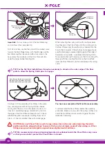
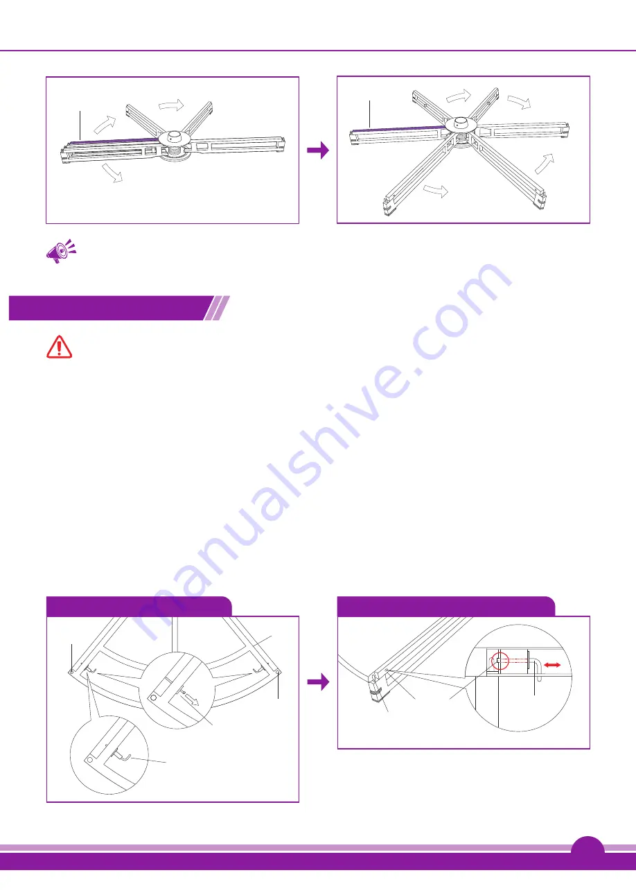
2 Frame legs Clockwise
3 Frame legs Anti-Clockwise
Fig. (8.3)
Fig. (8.4)
TIP: The legs fan out from the fixed frame leg clockwise or anti/counter-clockwise, it does not
matter which direction you choose. However, when dismantling, the moving frame legs should
always be folded back towards the fixed frame leg.
Fitting the floor plates
CAUTION: Be sure to remove all packaging material from the Floor Plates before you attempt to
fit them to the Main Stage Frame.
If you examine one of the Floor Plates, you will see that there are two Spring Catches on its underside, located at each
corner of the longer curved surface. Test the operation of the Spring Catches (Fig.9.1) before assembling to the Main
Stage Frame.
Lay the stage plate down on its face, the spring catch arm should be flat against the plate (Fig 9.1) Pull the end of the arm
upwards to a vertical position and the catch pin will automatically pop out of the floor plate. Each spring catch is spring
loaded so that when you release it (turn it through 90 degrees) To disengage, pull the catch arm inwards and rotate flat
against the plate.
This is a safety feature to ensure that the Spring Catches do not accidentally retract in use, releasing the Floor Plates.
The Spring Catches insert into the Floor Plate Locating Pin Holes (Fig.9.2) – together these are designed to secure each
floor plate to the Main Stage Frame. Once you have tested these, pull the spring catch back and return flat to the base
to reset. Make sure that the pins are now flush to the edge of the inner floor plate. These are now ready to install onto the
main frame.
Floor Plate
Locating Pin
Holes
Floor Plate
Locating Pin Holes
Spring Catch
(Pull outwards)
Inner Floor
Plate
Catch Arm flat
(Disengaged)
Fig. (9.1)
Single Floor Plate (underneath view)
Floor Plate Locating Pin
Spring Catch Hole
Spring Catch
Fig. (9.2)
Single Floor Plate
2
3

