RapidMatch
TM
GO Spectrophotometer
8
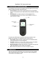
6. Contact Sensors, Indicators and LEDs
The indicators in the screen are arranged in the same pattern as the contact
sensors located around the measurement port.
•
Green Indicator:
ideal contact is being applied to the corresponding
sensor. A measurement can be taken when all three indicators illuminate
green.
•
Red Indicator:
the required contact is not being applied to the
corresponding sensor. Correct contact must be applied to achieve a
green indicator condition.
The multi-color LED located on the front of instrument provides visual
feedback on the status of a measurement and contact sensors.
•
Green LED:
Indicates all three contact sensors are activated properly
and a measurement can now be triggered.
•
Red LED
: Indicates one or more of the contact sensors is not properly
activated or an error has occurred during a measurement.
•
Blue Pulsing LED
: Indicates the instrument is in standby mode with the
USB cable plugged into the computer and charging.
•
Off
: Indicates the instrument is off and not ready to measure.
7. Home Screen
When the instrument is powered-up, the home (top level) screen appears
after the startup procedure is complete. Select the modes by tapping the
icons located on the display screen.
Contact sensor
indicator
LEDs
Contact sensor
indicator
Contact sensor
indicator
Summary of Contents for AMW106
Page 1: ...User Guide ...


