background image

C I 6 2 L + R T L   S P E C T R O P H O T O M E T E R  

17


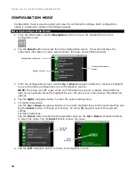
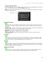
Exiting Configuration Mode 

After configuring options, use the Left navigation button to move the highlight focus to the Main 
screen icon in the Main column and tap the Select button to exit. 

NOTE: If a setting has a checkmark save icon it must be selected before exiting or any changes 
that were made will be lost. 


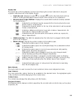
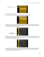
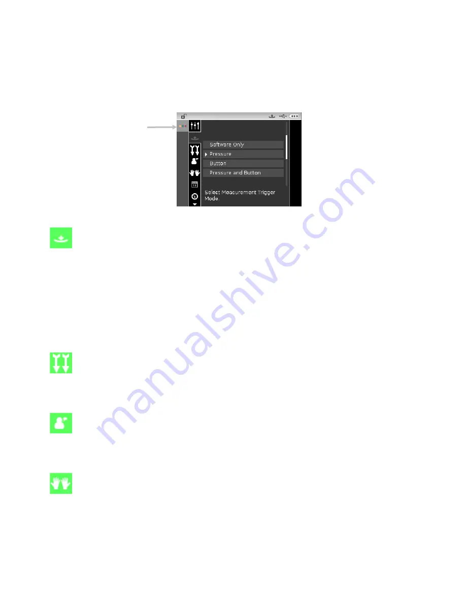
Measurement Trigger 

 This option is used to determine which inputs are used to trigger a measurement on the 

instrument. The available settings are Software Only, Pressure (default), Button, and Pressure 
and Button. 
Software Only: No button or read switch is required to take a measurement. This setting would 
be selected when software input is used to trigger a measurement. 
Pressure: Shoe closing is required to take a measurement. 
Button: Measure button is required to take a measurement. 
Pressure and Button: Both the read switch and measure button are required to a take a 
measurement. 

Averaging 

 This option is used to set the number of measurements required for calculating a single 

measurement. Measurements are taken at different locations on a sample to achieve average 
measurement values. The available settings are 1 to 99 (default is 3). 

Language 

 This option is used to set the language that is displayed on the instrument. The available 

settings are English (default), German, French, Spanish, Italian, Portuguese, Chinese Simplified, 
Chinese Traditional, Korean, and Japanese. 

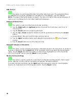
Instrument Orientation 

 This option is used to change the display direction to accommodate both right and left 

handed users. The available settings are Right Handed (default) and Left Handed. 

Main screen icon 

Summary of Contents for Ci62L+RTL

Page 1: ...Ci62L RTL Spectrophotometer User Guide...

Page 2: ......

Page 3: ...ration of this equipment in a residential area is likely to cause harmful interference in which case the user will be required to correct the interference at his own expense Industry Canada Compliance...

Page 4: ...may cause harmful interference to radio communication However there is no guarantee that interference will not occur in a particular installation If this equipment does cause harmful interference to...

Page 5: ...specifications iii repair or service by anyone other than X Rite or its authorized representatives iv the failure of the warranted goods caused by use of any parts or consumables not manufactured dis...

Page 6: ...ITE BE LIABLE FOR ANY OF BUYER S MANUFACTURING COSTS OVERHEAD LOST PROFITS GOODWILL OTHER EXPENSES OR ANY INDIRECT SPECIAL INCIDENTAL OR CONSEQUENTIAL DAMAGES BASED UPON BREACH OF ANY WARRANTY BREACH...

Page 7: ...14 Measure Mode 14 Calibration Mode 14 Configuration Mode 14 Display Screen Layout 14 Header Bar 15 Main Column 15 View Column 15 Content Area 15 Progress Column 15 Configuration Mode 16 Entering Con...

Page 8: ...Adding Standards to a Project 33 Deleting Projects Standards and Samples 34 Locking a Project 34 Editing Project Name 34 Appendices 36 Service Information 36 Cleaning the Instrument 37 General Cleanin...

Page 9: ...igation control for easy screen selections measure button and power on off Packaging Your instrument packaging should contain all the items listed below If any of these items are missing or damaged co...

Page 10: ...nt and around your wrist The strap should not be used to carry the instrument 1 Feed the small looped end of the strap around the post at the back of the instrument 2 Insert the wrist strap end throug...

Page 11: ...gnostics test and displays a splash screen before the main menu screen appears Splash Screen Main Menu Locking the Navigation Control The power button is also used to lock the navigation control This...

Page 12: ...p to 4 hours for full charge A charged battery pack may eventually lose partial charge if not used for an extended amount of time You should charge the battery from time to time and store in a cool en...

Page 13: ...the detachable line cord in the AC adapter and plug the line cord into the wall receptacle Connecting the USB Cable IMPORTANT You must install the software before connecting the instrument to your com...

Page 14: ...turning the instrument off and then back on will reset their operation Measure Button The Measure button is located at the front of the instrument The button can be configured to initiate a measuremen...

Page 15: ...e same height as the item for the rest of the instrument s shoe to sit on Procedure 1 Clear the sample surface of any dirt dust or moisture 2 Position the target window over the sample to measure If p...

Page 16: ...measurement options Refer to the Measurement Mode section for information Calibration Mode The calibration mode is used to perform white reference and black trap calibrations Refer to the Calibration...

Page 17: ...icts the current condition of the battery pack Indicates the battery pack is fully charged Indicates the battery pack has a sufficient charge for a substantial number of measurements Indicates the bat...

Page 18: ...ation icon in the Options column NOTE The arrow icon or at the end of the Options column indicates that additional options are available Move the highlight focus to the arrow icon to advance to the ad...

Page 19: ...er a measurement Pressure Shoe closing is required to take a measurement Button Measure button is required to take a measurement Pressure and Button Both the read switch and measure button are require...

Page 20: ...3 until the date and time are set 5 Tap the Right navigation button and highlight the checkmark icon in the Progress Column 6 Tap the Select button to save the date and time Delete All Samples or Sta...

Page 21: ...r to Appendices for calibration reference cleaning procedures The black trap should be cleaned periodically to remove any dust or contamination Refer to Appendices for black trap cleaning procedures D...

Page 22: ...alibration reference 5 Position the instrument target window over the white ceramic plaque 6 Press the instrument firmly to the shoe and hold steady until the display indicates that the reading is com...

Page 23: ...ol to save the calibration and exit to the main menu 11 Store the calibration reference in a dry dust free area away from direct exposure to light NOTE If an error message appears during or after whit...

Page 24: ...e averaged measurements was close to the preset limits A red icon indicates the variation of the averaged measurements has exceeded the preset limits Compare Mode Icons A description of the icons foun...

Page 25: ...measurement the instrument displays Averaged 1 of 3 in the screen indicating two more measurements are required for results 8 Position the instrument on the second area of the standard and take a meas...

Page 26: ...he instrument displays Averaged 2 of 3 in the screen indicating one more measurement is required for results 12 Position the instrument on the third area of the sample and take a measurement After the...

Page 27: ...ess column 2 Use the Up or Down navigation buttons to select the Save Standard icon 3 Tap the Select button to open the confirm screen to save the standard 4 Tap the Right navigation button and highli...

Page 28: ...lection and edit screen Arrow points to current standard selected Exits the averaging measurement sequence for the current sample Toggle between L C h Gloss and Y data views Toggle between the current...

Page 29: ...measurements are required for results 10 Position the instrument on the second area of the sample and take a measurement After the measurement the instrument displays Averaged 2 of 3 in the screen in...

Page 30: ...P H O T O M E T E R 28 NOTE If an error occurs during a measurement try measuring the sample again If the error still occurs refer to the Troubleshooting section in the Appendices Sample data Differen...

Page 31: ...t to delete and move the highlight to the Progress Column 2 Highlight the Delete icon and tap the Select button to display the Delete Standard screen 3 Highlight the Checkmark icon in the Progress Col...

Page 32: ...ect button 9 Continue until all characters for the name are set 10 Tap the Right navigation button and highlight the Checkmark icon in the Progress Column 11 Tap the Select button to save the name for...

Page 33: ...ine indicates that it is selected 4 Tap the Select button to access the option 5 Use the Up or Down navigation buttons to select the tolerance type 6 Tap the Select button to set the tolerance type 7...

Page 34: ...he procedures that follow Selecting a Project To select a project 1 From the Measure screen use the Up or Down navigation buttons to move the highlight focus to the Project icon 2 Tap the Select or Ri...

Page 35: ...e Select button 9 Use the Up or Down navigation buttons as previously explained to set the character and tap the Select button 10 Continue until all characters for the name are set 11 Tap the Right na...

Page 36: ...Standards Delete All Samples or Delete This Project Tap the Select button to choose the option 4 Tap the Right navigation button and highlight the Checkmark icon in the Progress Column 5 Tap the Selec...

Page 37: ...Use the Up or Down navigation buttons to page through the alphanumeric list for the character location of the name NOTE You can also use the navigation control to rapidly scroll through a list by tou...

Page 38: ...und the world You can contact us using one of the following methods To identify the X Rite service center nearest you please visit our web site at www xrite com For online help visit our web site www...

Page 39: ...in water or mild cleaner NOTE DO NOT use any solvents to the clean the instrument this will cause damage to the cover Cleaning the Optics The optics should be cleaned once a week in a normal environm...

Page 40: ...remove the ceramic plaque from the base 3 Clean the plaque using a mild soap and warm water solution Thoroughly rinse with warm water and wipe dry with a lint free cloth Do not use solvents or cleaner...

Page 41: ...with your fingers and separating 2 Clean with clean dry air or wipe clean with a lint free cloth to remove any dust or contamination 3 After cleaning align the two arrows on the end before reassemblin...

Page 42: ...ccess cover latch while lifting upwards on the cover to remove it from the instrument housing 3 Remove the old battery pack and dispose in a designated disposal location for recycling 4 Insert the new...

Page 43: ...ation procedure fails Calibration reference is dirty or damaged Clean the reference per procedure in Appendix or replace if damaged Instrument and software not communicating Interface cable not connec...

Page 44: ...b on any tile specular component included Short Term Repeatability 05 E ab on white ceramic standard deviation Lamp Life Approx 500 000 measurements Power Supply Removable Li ion battery pack 7 4 VDC...

Page 45: ...color check 3 Remove the protective cap from the green tile in the calibration reference 4 Position the instrument s target window over the green tile 5 Press the instrument firmly to the shoe Hold s...

Page 46: ......

Page 47: ......

Page 48: ......

Page 49: ...quarters X Rite Europe GmbH Althardstrasse 70 8105 Regensdorf Switzerland Phone 41 44 842 24 00 Fax 41 44 842 22 22 Asia Pacific Headquarters X Rite Asia Pacific Limited Suite 2801 28th Floor AXA Towe...

Reviews: