background image

C i 7 X X 0   B E N C H T O P   S P E C T R O P H O T O M E T E R  

27


3.


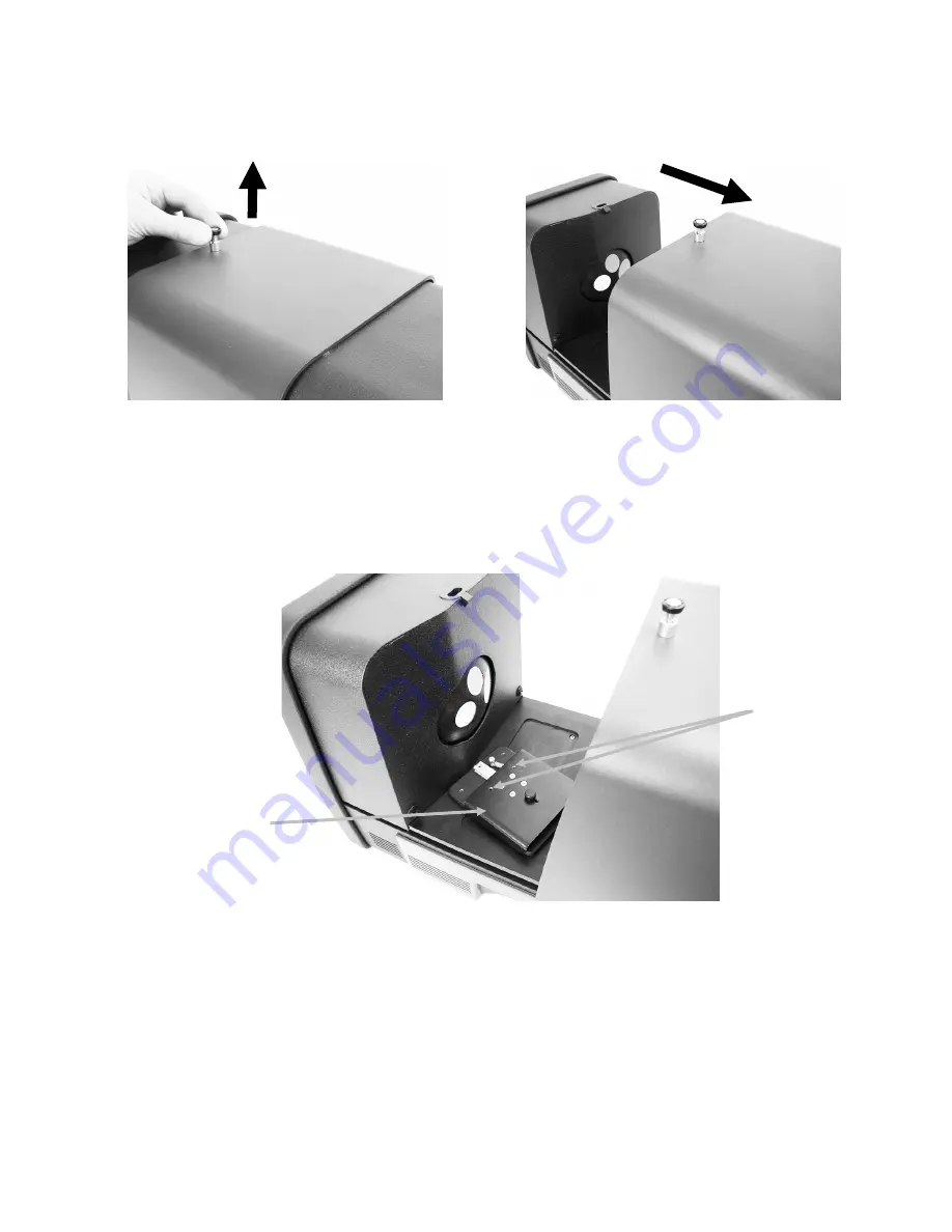
Open the transmission cover by lifting up on the locking pin while sliding the cover to the 
back. 


4.


Align the sample holder base plate pins to the base plate mounting channel holes inside the 
transmission area.  

Position the base plate with the clamp mounting holes on the sphere side. Be careful to get 
the angle correct. Care should be taken to properly align the base plate so that the sample is 
positioned between the stop and clamp toward the sphere. 


5.


Attach the appropriate sample stop to the base plate and clamp to the carriage base with the 
thumb screws. We recommend using a stop plate with all sizes including 25 mm. 
The sample is held in position using a sample stop on the sphere side of the sample, and a 
spring loaded clamp on the side of the sample away from the sphere. 

Care should be taken to properly align this holder so that the stop plate is positioned flush 
and tight against the opening in the sphere. Do not tighten the thumb screws until the 
sample has been positioned tight against this opening. 

Lens Side 

Sphere Side 

Clamp mounting holes 

Base plate in total 

transmission position 

Summary of Contents for Ci7860 Series

Page 1: ...Ci7XX0 Benchtop Spectrophotometer User Guide ...

Page 2: ......

Page 3: ... instruction manual may cause harmful interference to radio communications Operation of this equipment in a residential area is likely to cause harmful interference in which case the user will be required to correct the interference at his own expense Industry Canada Compliance Statement CAN ICES 3 A NMB 3 A Equipment Information Use of this equipment in a manner other than that specified by X Rit...

Page 4: ...Rite s accompanying documentation or published specifications iii repair or service by anyone other than X Rite or its authorized representatives iv the failure of the warranted goods caused by use of any parts or consumables not manufactured distributed or approved by X Rite v any attachments or modifications to the warranted goods that are not manufactured distributed or approved by X Rite Consu...

Page 5: ...ADDITION TO THE FOREGOING IN NO EVENT WILL X RITE BE LIABLE FOR ANY OF BUYER S MANUFACTURING COSTS OVERHEAD LOST PROFITS GOODWILL OTHER EXPENSES OR ANY INDIRECT SPECIAL INCIDENTAL OR CONSEQUENTIAL DAMAGES BASED UPON BREACH OF ANY WARRANTY BREACH OF CONTRACT NEGLIGENCE STRICT TORT OR ANY OTHER LEGAL THEORY IN ANY EVENT OF LIABILITY X RITE S MAXIMUM LIABILITY HEREUNDER WILL NOT EXCEED THE PRICE OF T...

Page 6: ... Street SE Grand Rapids Michigan 49512 Phone 888 826 3059 option 1 GPL and LGPL The GPL code and LGPL code used in this product are distributed WITHOUT ANY WARRANTY and is subject to the copyrights of one or more authors For details see the GPL code and the LGPL code for this product and the terms of the GPL and LGPL http www gnu org copyleft gpl html http www gnu org licenses lgpl html MIT This p...

Page 7: ... Group libxcb 1 7 Copyright C 2001 2006 Bart Massey Jamey Sharp and Josh Triplett libXcomposite 0 4 3 Copyright 2001 2003 Keith Packard Copyright c 2006 2007 Oracle and or its affiliates All rights reserved libXdamage 1 1 3 Copyright 2001 2003 Keith Packard Copyright 2007 Eric Anholt libXdmcp 1 1 0 Copyright 1989 1998 The Open Group libXext 1 2 0 Copyright 1986 1987 1988 1989 1994 1998 The Open Gr...

Page 8: ... Keith Packard Copyright 2000 SuSE Inc libXt 1 1 1 Copyright 2001 2003 Keith Packard Copyright c 1993 2011 Oracle and or its affiliates All rights reserved Copyright 1987 1988 by Digital Equipment Corporation Copyright 1987 1988 1998 The Open Group libXxf86vm 1 1 1 Copyright c 1995 Kaleb S KEITHLEY libdrm 2 4 26 Copyright 1999 Precision Insight Inc Cedar Park Texas Copyright 2000 VA Linux Systems ...

Page 9: ...ation are permitted provided that the following conditions are met 1 Redistributions of source code must retain the above copyright notice this list of conditions and the following disclaimer 2 Redistributions in binary form must reproduce the above copyright notice this list of conditions and the following disclaimer in the documentation and or other materials provided with the distribution THIS ...

Page 10: ...Reflectance Measurements 25 Transmission Measurements excludes Ci7500 series 26 Total Transmission Measurement 26 Direct Transmission Measurement 28 R T Reflection Total Transmission Measurement 30 Liquid Measurements 32 Haze Measurements 33 Appendices 34 Service Information 34 Cleaning the Instrument 35 Cleaning Quick Reference Table 35 General Exterior Cleaning 36 Cleaning the Transmission Compa...

Page 11: ...stment for measuring fluorescent or optically brightened samples USB interface to PC and software applications Indicator panel display with dual buttons for standard and sample measurements and warning indicators for calibration interval Dampened sample arm holder that prevents sample damage Embedded white sample holder ceramic Ideal for reflectance measurements that require a white backing such a...

Page 12: ...tional Ci7600 Series aperture plates 25 mm 10 mm 6 mm 3 5 mm optional 17 mm optional Ci7500 Series aperture plates 25 mm 10 mm White UV plaque Instrument Setup Please follow the instructions detailed in the Ci7XX0 Installation Instructions sheet found as the first item in your shipping box when you opened it A PDF file of the Installation Instructions also can be found on the Ci7XX0 Driver and Doc...

Page 13: ...may assign a different behavior to the button for various reasons Live Preview Video in PC Software Application This method requires a software application such as Color iQC to provide a means to view video within the application Follow the instructions in your application to preview video for sample alignment Note DO NOT power down the instrument into Standby mode when preview video is actively s...

Page 14: ...iew feature The indicator illuminates green when it is activated The video preview is toggled when a reflectance measurement mode is selected When a transmission measurement mode is selected the button will toggle the green transmission targeting laser on and off The behavior of the button may also be programmed in your software application Trial Button and Indicator The trial button is used to in...

Page 15: ...V Excluded Illuminated when one of the UV filters fully blocks the UV component in the lamp to fully exclude UV illumination Custom Illuminated when a user defined D65 or other UV condition is selected 400 The 400 nm UV cutoff filter is in use This filter is adjustable and can be used to calibrate UV conditions 420 excludes Ci7500 series The 420 nm UV cutoff filter is in use This optional filter i...

Page 16: ... position the shelf s elongated slots over the two holes in the sample door and attach it with the thumb screws provided Adjust the shelf by loosening the thumbscrews and sliding the shelf up or down Sample Holder The sample holder can be locked in a down position This is convenient when large samples are measured or when the aperture plate is changed or the sample holder is removed Simply open th...

Page 17: ...he top by using your fingers and gently lower the door to the complete open position See the figure below 3 With the sample door completely open view the sample at the view port and make sure the sample is in an optimal position for measuring 4 Close the sample door and prepare for the measurement Specular Control You can change the specular component setting on the spectrophotometer for reflectan...

Page 18: ...ionally include a 420 and or 460 nm UV filter as well Aperture Control By default the spectrophotometer is configured to auto recognize an aperture plate when installed at the measurement port and to auto drive the lens to the matching size The lens position is also dependant on the measurement mode If for example the instrument is configured with the 10 mm aperture plate in a reflectance measurem...

Page 19: ... on the sample door The plate is held in place by magnets 4 Gently close the sample holder 5 The aperture plate will be automatically recognized when the door is closed and activate the auto zoom lens if set to the auto mode Auto recognition is only valid for Reflectance mode aperture plates For transmission aperture plates the asterisk LED lights up green ...

Page 20: ...s Refer to Appendices for calibration tile cleaning procedures The black trap should be cleaned periodically to remove any dust or contamination Refer to Appendices for black trap cleaning procedures Reflectance Calibration Procedure To calibrate your spectrophotometer in reflectance measurement mode you need to use your software application Follow these steps 1 Verify the 25 mm aperture plate is ...

Page 21: ...not calibrated 10 Continue with additional configuration calibrations as required Green Tile Color Check optional 1 Perform a calibration procedure if you have not already done so Refer to the Calibrating section 2 Remove the green tile from the accessory drawer Pull down on the sample holder and position the tile on the sample holder clamp Make sure the green ceramic side is facing the aperture p...

Page 22: ...locking panel Note NEVER use the black trap for black calibration when performing Transmission calibration Transmission Calibration Setup Note For R T Reflection Total Transmission perform a Reflectance Calibration before continuing 1 Using your software application launch the calibration process from the software interface 2 Mount the 25 mm aperture plate with white reflective ring to the measure...

Page 23: ...mission holder base inside the transmission compartment 2 Attach the appropriate clamp and stop to the base with the thumb screws 3 Center the black plastic blocking panel in the transmission sample holder and place between the stop and clamp toward the sphere 4 Close the cover and continue with calibration Black plastic blocking panel Carriage base Total transmission calibration shown ...

Page 24: ... Remember that each configuration needs to be calibrated Direct Calibration 1 Place the sample transmission holder base inside the transmission compartment 2 Attach the appropriate clamp and stop to the carriage base with the thumb screws 3 Center the black plastic blocking panel in the transmission sample holder and position toward the lens side 4 Close the cover and continue with calibration Bla...

Page 25: ...p to the carriage base with the thumb screws 3 Center the black plastic blocking panel in the transmission sample holder and position toward the sphere 4 Close the cover and continue with calibration 5 Once the calibration process is complete the calibration LED becomes lit Any change to the spectrophotometer configuration may result in the calibration LED turning from green calibrated to red not ...

Page 26: ... calibration plaque from the protective bag in the accessory drawer 5 Pull down on the sample holder and position the UV calibration plaque against the 25 mm aperture plate Make sure the white surface is facing the aperture plate 6 Close the sample holder clamp to the UV calibration plaque 7 Initiate the UV calibration measurement from the software 8 Follow the procedure in the application 9 Remov...

Page 27: ...ample and adjust the sample measurement targeting area Caution Do not look directly into the measurement optics when the instrument is on 7 Trigger the measurement using one of the following methods a Select Measure Standard or Measure Trial from your software Follow the software instructions for loading the sample at the view port OR b Press the Standard or Trial button on the instrument front pa...

Page 28: ...easured using the cuvette sample holder Always make certain that the sample is flush and parallel to the opening in the sphere or the lens If transmission white plaque gets soiled it must be replaced Close the cover when measuring Use aperture plates with white reflective ring Use the transmission white plaque not smooth glossy calibration tile Transmission Sample Holder Description Total Transmis...

Page 29: ...he stop and clamp toward the sphere 5 Attach the appropriate sample stop to the base plate and clamp to the carriage base with the thumb screws We recommend using a stop plate with all sizes including 25 mm The sample is held in position using a sample stop on the sphere side of the sample and a spring loaded clamp on the side of the sample away from the sphere Care should be taken to properly ali...

Page 30: ...mple positioned towards the lens in the back of the instrument Direct Transmission is appropriate for measuring transparent samples which exhibit no scattering of the light This would generally be samples colored with dyes rather than pigments When measuring with this method the diffuse light is collimated this means that the light rays are travelling in a parallel fashion as they pass through the...

Page 31: ... Attach the 25 mm sample stop to the base plate and 25 mm clamp to the carriage base with the thumb screws The sample is held in position using a sample stop on the lens side of the sample and a spring loaded clamp on the side of the sample away from the lens Do not tighten the thumb screws until the sample has been positioned tight against this opening 6 Pull the clamp back and position the sampl...

Page 32: ...tion port reflection measurement The second measurement is taken with the sample positioned flush against the stop at the back of the sphere total transmission measurement When measuring with this method the diffuse light travels through the object from all angles Again the sample is illuminated from all possible angles with a diffuse light source 1 Mount the aperture plate with white reflective r...

Page 33: ...all sizes including 25 mm 8 Remove the sample from the sample holder Care should be taken to properly align the base plate so that the sample is positioned between the stop and clamp toward the sphere When setting up for measurements do not tighten the thumb screws until the sample has been positioned properly 9 Once properly position tighten the thumb screws and close the transmission cover 10 In...

Page 34: ...ld be positioned between the cuvette and the opening in the sphere Cuvette Cleaning and Handling Care should be taken to ensure the cuvette and holder is kept clean Carefully wash the holder and cuvette in warm soapy water and rinse thoroughly Never touch the cuvette windows with your fingers as the oils in your skin will etch the windows Handle the cuvette by the edges Always leave an air gap bet...

Page 35: ...ive ring transmission white plaque and black trap positioned at the reflectance port Before you can take a Haze measurement you need to calibrate for the haze measurement first unless you are already in Haze Measurement mode using a current haze calibration Procedure 1 Mount the 25 mm aperture plate with the white ring at the measurement port as previously explained 2 Select Haze as the measuremen...

Page 36: ...To identify the X Rite service center nearest you please visit our web site at www xrite com and click the Contact Us link For online help visit our web site www xrite com and click the Support link Here you can search for software or firmware updates white papers or frequently asked questions which can quickly resolve many common user problems Send an e mail to Technical Support detailing your pr...

Page 37: ...ompressed air If can air is used for any of the cleaning procedures that recommend air do not invert or tilt the can during use This could cause damage CAUTION When using chemicals always follow the manufacturer s personal protection equipment recommendations in the chemical SDS Cleaning Quick Reference Table Below is a quick reference to help you determine the proper cleaning methods Refer to the...

Page 38: ...lace the tile on a stable surface and hold the tile by its edges 2 Spray a small amount of Isopropyl Alcohol onto a portion of a lint free wipe then wipe with a circular motion making sure to clean the entire surface Use a dry portion of the wipe to wipe the surface of the tile until dry Discard the wipe 3 Spray a liberal amount of glass cleaner onto the surface of the tile Using a clean lint free...

Page 39: ...r across the surface to remove any dust or contamination Cleaning the Black Trap The black trap should be cleaned from time to time to remove and dust or contamination that may collect inside 1 Remove the base 1 from the trap 2 by turning to the left and lifting upwards 2 Look inside of the black trap to reference how the trap glass is positioned This is important to remember when it comes time to...

Page 40: ...be resting against the felt pad 5 in the bottom of the trap when positioned properly 6 Align the base notches over the tabs in the trap and turn to the right until it snaps into position NOTE The base tabs are keyed to only allow installation in one position Make sure you do not force it on the trap Cleaning the UV Calibration Plaque Do not use solvents or cleaners of any kind Blow short burst of ...

Page 41: ...the carrier is firmly seated 5 Reinstall the detachable line cord Adjusting the Sample Holder Dampening If required the sample holder dampening effect can be changed when closing the sample holder Simply adjust the pin in the sample holder to increase or decrease dampening 1 Remove the sample holder from the front of the instrument by loosening the two screws Refer to the Ci7XX0 Installation Instr...

Page 42: ...pendix or replace if damaged If damaged arrange for replacement by contacting X Rite Support Instrument and software not communicating Interface cable not connected Connect the interface cable between the computer and the instrument Close and restart the software application If this does not work reboot the computer Turn the instrument off wait 30 seconds then turn the instrument on and see if the...

Page 43: ...ation Pulsed Xenon D65 Calibrated Pulsed Xenon D65 Calibrated Pulsed Xenon D65 Calibrated Pulsed Xenon D65 Calibrated Measurement time 2 7 4 0 seconds flash data acquisition 2 7 4 0 seconds flash data acquisition 2 7 4 0 seconds flash data acquisition 2 7 4 0 seconds flash data acquisition Duty cycle 480 measurements per hour max 480 measurements per hour max 480 measurements per hour max 480 meas...

Page 44: ...oltage Category Category II EMC Compliance IEC EN 61326 1 Operating Temperature Storage Temperature 5º C to 40º C 40º C to 70º C Altitude operating 2000 m Pollution Degree 2 Operating Humidity Storage Humidity 5 to 85 relative non condensing 5 to 85 relative non condensing Dimensions 23 cm W x 25 cm H x 47 cm D Weight 20 5 kg Interface USB Design and specifications subject to change without notice...

Page 45: ... sample holder and a storage case CIA 800 02 Ci7800 Ci7860 Transmission kit this kit includes a calibration standard a transmission cuvette with holder a transmission sample holder and a storage case CIA 800 01 25 mm Glass Aperture A AP GLAV57 NetProfiler 3 Industrial Benchtops 1 Year License NP3 IB1 NetProfiler 3 Industrial Benchtops 1 Year License without Tile Set NP3 IB1NT NetProfiler 3 Industr...

Page 46: ...connect to PC via USB ii Insert the Ci7XX0 Benchtop Spectrophotometer CD into your optical drive If the main startup menu does not automatically launch run the start exe program from the Setup Tool folder of the CD iii Select Setup Tool from under the Utilities section of the software CD main menu Run the Setup program iv Select Lock Optics from the main menu of the Setup program You can hear the ...

Page 47: ...re into its own bag if available from original packaging iii Insert all of the bagged apertures into a single bag combined f Install protective bag over instrument s front plate i Open front sample door from top not through sphere opening ii Slide protective bag over front plate if available from original packaging iii Close sample door g Insert rubber shim on door latch if available from original...

Page 48: ...rawer ii Place black trap into plastic bag if available from original packaging j Prepare accessory drawer i Open accessory drawer ii Ensure all apertures and black trap are removed see steps above iii Return white calibration standard into drawer iv Return green calibration standard into drawer v Place UV calibration standard into its small bag if available from original packaging and insert UV c...

Page 49: ...accessory drawer 3 Prepare box for instrument a Install bottom foam piece into shipping box b Place bag in box i Insert large bag for instrument into box if available from original packaging ii Open bag over top of box UV tile Green tile White tile Carton seam Back of foam insert ...

Page 50: ... by front and rear grips ii Lift and lower instrument into box oriented in foam as shown b Wrap bag around instrument c Place the top instrument foam piece on top of instrument and position the foam to the instrument as shown Shown without bag for clarity Door forward Lock button UP Front of instrument Front of instrument Small foam block ...

Page 51: ... E T E R 49 5 Install contents into foam tray compartments as shown and place tray into the box Aperture kit Cleaning kit Place these items in this compartment Sample shelf Line cord Sample holder USB cable Place these items in this compartment Black trap ...

Page 52: ...C i 7 X X 0 B E N C H T O P S P E C T R O P H O T O M E T E R 50 6 Place top cardboard protective sheet on top of foam tray if available from original packaging 7 Close and tape the box ...

Page 53: ......

Page 54: ...eadquarters X Rite Europe GmbH Althardstrasse 70 8105 Regensdorf Switzerland Phone 41 44 842 24 00 Fax 41 44 842 22 22 Asia Pacific Headquarters X Rite Asia Pacific Limited Suite 2801 28th Floor AXA Tower Landmark East 100 How Ming Street Kwun Tong Kowloon Hong Kong Phone 852 2568 6283 Fax 852 2885 8610 Please visit www xrite com for a local office near you P N Ci7XX0 EN Rev H ...

Reviews: