background image

ENCORE

7

When installing a belt refer to fig. 4 as to the 

route of the belt.

BELT ADJUSTMENT 

(continued...)

TRACKING

To adjust the tracking there is a stop bolt 

located on the bottom side of the steering 

control. (See Fig. 5) 
To adjust tracking simply loosen the lock 

nut on the stop bolt and turn bolt clockwise 

to increase speed or counter clockwise to 

decrease speed. 

DRIVE ADJUSTMENTS

Steering and motion controls should be 

uniform in all forward and reverse speeds.  

Levers should automatically return to neutral 

when released.

 

CAUTION:

TURN OFF ENGINE BEFORE MAKING ANY 

ADJUSTMENTS.

To test drive operations:

 

Check air pressure in tires.  Equal tire  


pressure is critical for proper drive    


operation.

 

Check linkage for excessive play.


• 

Raise rear of Rider until rear wheels  


  are off the ground.  Safely block the  


  frame in this position.


• 

Put control levers in neutral lock    


  position (control levers swung    


  outward).


• 

Start engine.

DECK HEIGHT ADJUSTMENT 

Mower heights can be adjusted by pushing the 

foot pedal and by depressing the height of cut 

pin and removing it. Select cutting height and 

set pin accordingly. 

TENSION

IDLER

BLADE

IDLER

CLUTCH

PULLEY

Fig. 4 - Mower Deck Belt Layout

Fig. 5

Stop Bolt

Cut Pin

CU

TT

IN

G

 H

EIG

HT

Fig. 6

Summary of Contents for 48K19X

Page 1: ...OPERATORS MANUAL 48K19X ...

Page 2: ... the fuel tank indoors Wipe up any spilled gasoline Gasoline is highly flammable NO SMOKING 7 Handle gasoline carefully Use an approved gasoline container Fill the fuel tank to within 1 from the neck with good quality unleaded gasoline 8 Drive levers must be in the Neutral position and the Blade Clutch must be disengaged before starting engine 9 Operator must wear proper shoes and clothing which ma...

Page 3: ...efore hooking up the ground wires make sure that the engine has been filled to the proper level with oil If battery will not turn the engine over after hooking the wires up it may require a charge for 15 to 20 minutes Raise the unit slightly and place a board under each rear wheel With the deck in the raised position start the unit and drive it off the pallet Once you are familiar with the contents...

Page 4: ...anding and maintaining this system is vital for maximum safe operation TO START ENGINE 1 Blades PTO must be OFF 2 Control levers in neutral swung out 3 Park Brake ON 4 Operator in seat THE ENGINE WILL KILL IF 1 The operator leaves the seat with a The control levers out of neutral swung in b The blades on PTO c The park brake is OFF d All the above 2 The park brake is set before the control levers ...

Page 5: ...r setting 5 Allow time for the engine to cool down prior to storing mower Do not store mower or gasoline near any open flame or where gasoline fumes may be ignited 6 Always replace worn or broken parts with genuine Encore repair parts purchased from an authorized Encore dealer Using anything other than Encore repair parts may void all Encore factory warranties CAUTION DO NOT SPILL OIL OR GREASE ON ...

Page 6: ... eyes skin and clothing IN THE EVENT OF AN ACCIDENT Flush affected area immediately with a solution of one part baking soda to four parts water If baking soda is not readily available flush affected area with water Notify physician immediately LUBRICATION There are 5 grease points on the X52 One on each caster one on the caster swivel and one on the foot pedal pivot These are all pre greased from t...

Page 7: ...l when released CAUTION TURN OFF ENGINE BEFORE MAKINGANY ADJUSTMENTS To test drive operations Check air pressure in tires Equal tire pressure is critical for proper drive operation Check linkage for excessive play Raise rear of Rider until rear wheels are off the ground Safely block the frame in this position Put control levers in neutral lock position control levers swung outward Start engine DEC...

Page 8: ...lades should be kept sharp and well balanced File or grind blades evenly Take care to retain angle of original cutting edge CHARGING SYSTEM An alternator is used to charge the battery The alternator charging system normally requires no service other than periodically checking that all exposed wiring and electrical connections on the machine are clean tight and in good condition Proper polarity is ...

Page 9: ... deck equally or must have equal tension on them ELECTRICAL The fuse box is located under the seat on a panel mounted to the seat frame There are two 2 fuses that run the system the top fuse which is a 20 amp is the main fuse The second a 15 amp fuse takes care of the electric clutch The third and fourth slots are blank extras If there is a recurring fuse failure check the electrical system for a ...

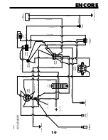
Page 10: ...E 15 AMP FUSE WIRE JUNCTION 52K23X 423351 WIRE HARNESS ELECTRICAL DRAWING ORANGE 12 GA LT BLUE 14 GA RED 12 GA WHITE 16 GA FUSE BLOCK 423027 IGNITION SWITCH RED BLACK STP 18 GA YELLOW 16 GA YELLOW 16 GA GREEN 18 GA GROUND TO ENGINE 593041 NEUTRAL SWITCH CLUTCH CONN BLACK 18 GA BLACK 14 GA BLACK WHITE 18 GA 423030 MODULE CONN BROWN 18 GA LT BLUE 14 GA GREEN 18 GA 523031 CLUTCH SWITCH 523283 HOUR ME...

Page 11: ... paid The engine is covered by its respective manufacturer please refer to the manufacture s warranty statement that is included in the literature packet Engine warranties should be referred to the nearest authorized service outlet of the engine manufacturer The responsibility of Encore Mfg Co Inc in respect to claim is limited to making the required repairs or replacements and no claim of breach ...

Page 12: ... ENCORE MANUFACTURING CO INC All rights reserved Contents subject to change Part Number 1004 B X TREME 48K19X OPERATORS MANUAL 933175 ...

Reviews: