background image

- 1 -

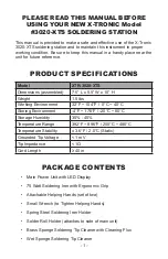
PLEASE READ THIS MANUAL BEFORE 

USING YOUR NEW X-TRONIC Model 

#3020-XTS SOLDERING STATION


This manual is provided to make a safe and effective use of the X-Tronic 

3020-XTS soldering station and to maintain this instrument in proper 

working condition. Be sure to keep this manual in a handy place near the 

unit for future reference.

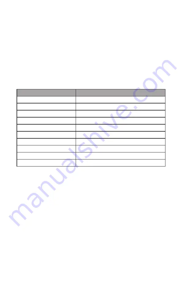
PRODUCT SPECIFICATIONS

Model

XTR-3020-XTS

Dimensions (assembled)

7.5” L x 5.5” W x 10” H

Weight

1.5 lbs

Working Environment

32°F ~ 104°F /  0°C ~ 40°C

Storing Environment

-4°F ~ 176°F / -20°C ~ 80°C

Storage Humidity

35% - 45%

Temperature Range

392°F ~ 896°F / 200°C ~ 480°C

Temperature Stability

± 3.6°F / 2.0°C (Static)

Grounded Tip Voltage

< 1 mV

Tip Impedance

< 1Ω

Cord Length

≥ 40 in

PACKAGE CONTENTS

•  Main Power Unit with LED Display

•  75 Watt Soldering Iron with Ergonomic Grip

•  Attachable Helping Hands (set of two)

•  Small Wrench (to Tighten Helping Hands)

•  Spring Steel Soldering Iron Holder

•  Solder Roll Holder (attaches to side of main unit)

•  Brass Sponge Soldering Tip Cleaner with Cleaning Flux

•  Wet Sponge Soldering Tip Cleaner

Summary of Contents for 3020-XTS

Page 1: ......

Page 2: ......

Page 3: ...x 10 H Weight 1 5 lbs Working Environment 32 F 104 F 0 C 40 C Storing Environment 4 F 176 F 20 C 80 C Storage Humidity 35 45 Temperature Range 392 F 896 F 200 C 480 C Temperature Stability 3 6 F 2 0...

Page 4: ...ther than soldering 5 Do not tap the soldering tip against the work surface to remove residual solder this can damage the soldering tip and or heating element 6 Do NOT modify the unit in any way 7 Whe...

Page 5: ...ont of the control module The temperature of the soldering iron can be set anywhere from 392 F 896 F 200 C 480 C 8 Moving the temperature control potentiometer clockwise will raise the temperature on...

Page 6: ...sure that the outlet is functional Soldering Iron Rattles This is expected behavior The rattle is a small ball that allows the unit to determine when the soldering iron is not in use and it should go...

Page 7: ...p This will destroy the plating and shorten tip life Do not use chloride and acid fluxes they will also shorten tip and heater life For maximum tip life always apply solder to the heated connections o...

Page 8: ...etaining collar over the new soldering tip back onto the soldering iron 4 Tighten the metal tip retaining screw cap to secure the tip into place Do not over tighten the metal tip retaining screw cap 5...

Page 9: ...d and pull the heating element away from the board Please take note of the location of the wire thickness color for installation of new heating element see diagram below 5 On one side of the circuit b...

Page 10: ...2159 Magnum Circle Lincoln Nebraska 68522 we extend this limited warranty only to the consumer who originally purchased the product in the United States the District of Columbia or Canada you It does...

Page 11: ...With respect to any defective product during the Initial Warranty Period we will in our sole discretion either a replace such product or the defective part free of charge or b refund the purchase pric...

Page 12: ...ur NEW Product Seal prior to shipment Our goal is to ensure Quality Completeness and Satisfaction for your order For Any Questions Problems or Compliments please call or email us If you would like to...

Reviews: