background image

- 6 -

        WARNING        

DISCONNECT POWER CORD BEFORE REPLACING A 

SOLDERING TIP AND/OR A HEATING ELEMENT

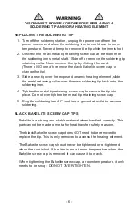
REPLACING THE SOLDERING TIP

1.  Turn off the soldering station, unplug the power cord from the 

power source and allow the soldering iron to cool down to room 

temperature. Never attempt to remove the tip while the iron is hot.

2.  Unscrew the small metal tip retaining screw cap at the bottom of 

the soldering irons metal shaft. Slide off or remove the soldering tip 

retaining collar. Now, remove the tip by sliding it forward.  

(There is NO need to remove the black Bakelite screw cap to 

change the tip.)

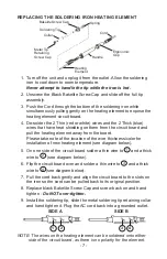
3.  Slide a new tip over the exposed ceramic heating element, slide 

the metal retaining collar over the new soldering tip back onto the 

soldering iron.

4.  Tighten the metal tip retaining screw cap to secure the tip into 

place. Do not over tighten the metal tip retaining screw cap.

5.  Plug the soldering iron AC cord into a grounded outlet to resume 

soldering.

BLACK BAKELITE SCREW CAP TIPS

•  Bakelite is a strong and stable material when handled correctly. This 

part cannot be made of metal for heat transfer safety reasons.

•  The black Bakelite screw cap does NOT need to be removed to 

replace the tip. This is only removed to access the heating element.

•  The Bakelite screw cap should never be tightened or re-tightened 

when the iron is hot. If the iron is not at room temperature when the 

Bakelite screw cap is removed it can cause it to crack.

•  When tightening the Bakelite screw cap, at room temperature, it only 

needs to be snug - DO NOT OVER-TIGHTEN.

Summary of Contents for 3020-XTS

Page 1: ......

Page 2: ......

Page 3: ...x 10 H Weight 1 5 lbs Working Environment 32 F 104 F 0 C 40 C Storing Environment 4 F 176 F 20 C 80 C Storage Humidity 35 45 Temperature Range 392 F 896 F 200 C 480 C Temperature Stability 3 6 F 2 0...

Page 4: ...ther than soldering 5 Do not tap the soldering tip against the work surface to remove residual solder this can damage the soldering tip and or heating element 6 Do NOT modify the unit in any way 7 Whe...

Page 5: ...ont of the control module The temperature of the soldering iron can be set anywhere from 392 F 896 F 200 C 480 C 8 Moving the temperature control potentiometer clockwise will raise the temperature on...

Page 6: ...sure that the outlet is functional Soldering Iron Rattles This is expected behavior The rattle is a small ball that allows the unit to determine when the soldering iron is not in use and it should go...

Page 7: ...p This will destroy the plating and shorten tip life Do not use chloride and acid fluxes they will also shorten tip and heater life For maximum tip life always apply solder to the heated connections o...

Page 8: ...etaining collar over the new soldering tip back onto the soldering iron 4 Tighten the metal tip retaining screw cap to secure the tip into place Do not over tighten the metal tip retaining screw cap 5...

Page 9: ...d and pull the heating element away from the board Please take note of the location of the wire thickness color for installation of new heating element see diagram below 5 On one side of the circuit b...

Page 10: ...2159 Magnum Circle Lincoln Nebraska 68522 we extend this limited warranty only to the consumer who originally purchased the product in the United States the District of Columbia or Canada you It does...

Page 11: ...With respect to any defective product during the Initial Warranty Period we will in our sole discretion either a replace such product or the defective part free of charge or b refund the purchase pric...

Page 12: ...ur NEW Product Seal prior to shipment Our goal is to ensure Quality Completeness and Satisfaction for your order For Any Questions Problems or Compliments please call or email us If you would like to...

Reviews: