16
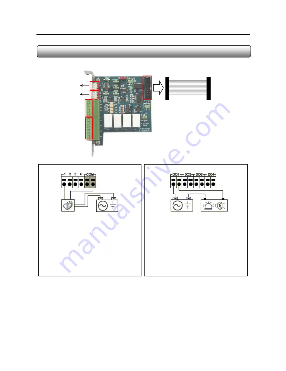
2.11 I/O Card
Alarm Output
Sensor Input
To Serial Port on PC
To DI/DO Terminal
on capture board
PTZ Signal Cable
RS422/485
.AC 125V, 500mA or below
.DC 110V, 0.3A or below
.DC 30V, 1A or below
3 D/O Voltage
- Control Output : DO Terminal Close
- Normal : DO Terminal Open
2. Operation
Connect both power lines to DO terminal
1. Connection
[ Alarm Output Terminal ]
Close
3. At normal close mode, it works reversely.
- Sensor Detection : 1-4 Terminal & COM Port
- Normal : 1-4 Terminal & COM Port Open
2. Operation
Connect one signal line to COM port and connect
Another signal line to the desired sensor number.
1. Connection
[ Sensor Input Terminal ]
Notes ;
- N/O : Normal Open
- N/C : Normal Close
- DI Operation Mode (N/O or N/C) can be selected from Setup Mode of Sentry Program
- D/O Delay Time can be adjusted from Setup Mode of Sentry Program
X-Vision
Summary of Contents for XP4SW25
Page 2: ...2 Chapter 1 Setup Introduction X Vision...
Page 5: ...5 Chapter 2 DVR Hardware X Vision...
Page 14: ...14 2 9 Audio board 2ch Formation XP16SW50 board Audio input guide Flat cable X Vision...
Page 15: ...15 2 10 Audio board 1ch Formation XP4SW25 board Audio input guide AV cable X Vision...


