background image

7

6

 C

ONTROLS


AND

 C

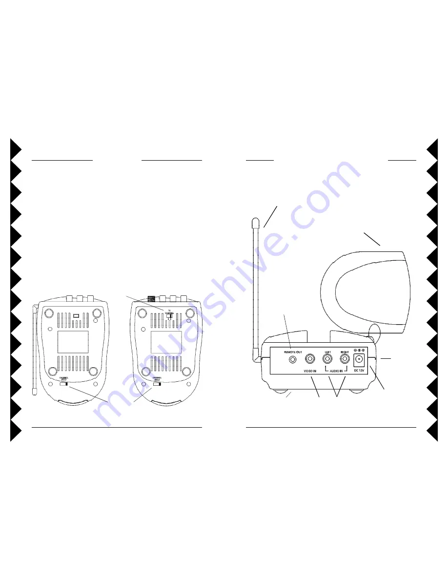
ONNECTIONS


V

IDEO

 S

ENDER

C

ONTENTS


C

ONTROLS


AND

  C

ONNECTIONS

...........................................

7

V

IDEO

 S

ENDER

...................................................................

7

V

IDEO

 R

ECEIVER

.................................................................

8

C

ONNECTING

  U

P

.................................................................

9

H

OOKING


UP


THE

  V

IDEO

  S

ENDER

.........................................

9

H

OOKING


UP


THE

  V

IDEO

  R

ECEIVER

.....................................

1 1

I

F


YOU


WANT


TO


USE


YOUR

  V

IDEO

  S

ENDER


TO


TRANSMIT

FROM


YOUR

 S

TEREO

 S

YSTEM


ONLY

......................................

1 2

F

INE


TUNING


YOUR

  V

IDEO

  S

ENDER

..................................

1 3

R

EMOTE

 E

XTENDER

 F

EATURE

..............................................

1 4

S

ENDER

(

BOTTOM

  V

IEW

)

R

ECEIVER

(

BOTTOM

  V

IEW

)

2.4 GHz

Channel

Switch

TV

Channel

Switch

Antenna for

IR Extender

Feature

IR Extender

Jack

A/V Input

Jacks

Power Supply

Jack

2.4 GHz

Video

Antenna

 ON-OFF

Switch

(on side)

2.4 GHz Channel

Switch

(on bottom)

Summary of Contents for RVK35

Page 1: ...OWNER S MANUAL Video Sender AUDIO VIDEO EXTENDER SYSTEM MODEL RVK35 INCLUDES RVT35 SENDER RVR35 RECEIVER...

Page 2: ...ed with care Quick stops excessive force and uneven surfaces may cause the product and cart combination to overturn 10 Ventilation Slots and openings in the cabinet are provided for ventilation and to...

Page 3: ...ifications to this product will void the user s authority to operate this equipment 11 Power Sources This product should be operated only from the type of power source indicated on the marking label I...

Page 4: ...1 IF YOU WANT TO USE YOUR VIDEO SENDER TO TRANSMIT FROM YOUR STEREO SYSTEM ONLY 1 2 FINE TUNING YOUR VIDEO SENDER 1 3 REMOTE EXTENDER FEATURE 1 4 SENDER BOTTOM VIEW RECEIVER BOTTOM VIEW 2 4 GHz Chann...

Page 5: ...on the TV are colored differently connect the yellow plug to thejacklabelledVIDEO theredplugtothejacklabelledAUDIORIGHT andthewhiteplugtothejacklabeledAUDIOLEFT Note If your TV does not include Audio...

Page 6: ...or 4 3 Plug the Video Sender s Power Supply the smaller of the two power supplies into a convenient 120 volt wall outlet and plug its jack into the VideoSender 4 Position the Video Sender in a conven...

Page 7: ...onthe bottom of the Video Receiver 3 or 4 IF THE SIGNAL IS POOR OR THERE IS INTERFERENCE Trychangingthechannelonbothunits DothisbyadjustingtheCHANNEL slide switch on the bottom of each Video Sender un...

Page 8: ...S EXPRESSED OR IMPLIED AND NO REPRESENTATIVE OR PERSON IS AUTHORIZED TO ASSUME FOR US ANY OTHER LIABILITY IN CONNECTION WITH THE SALEOFOURPRODUCTS SOME STATES DO NOT ALLOW LIMITATIONS ON HOW LONG AN I...

Page 9: ...16 X10 USA Inc 3824 North 5th St Suite C North Las Vegas NV 89030 Web Site www x10retail com RVK35 11 99...

Reviews: