18
19
Ensure that the power cable is unplugged before connecting further components.
Components already connected to the device should also be unplugged from the po-
wer supply.
Make sure connections have been made accurately, this means for example left to left and right
to right.
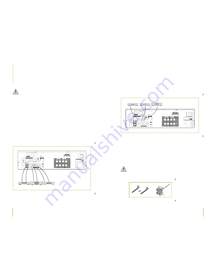
Connecting analog end devices
Only use standard, shielded audio cables when connecting audio sources. Other cables may
cause interference. Only connect devices equipped with the appropriate jacks, in order to avoid
distortion and mismatching, which in turn could cause damage to the device. Before connec-
ting jacks, make sure the correct terminal has been selected. Audio cables/plugs, as well as the
terminals on most devices, are normally red and white to help distinguish what plug is to be
connected to what jack.
Chapter 5
Making connections
Chapter 5
Making connections
5
Making connections
Connecting devices to digital connections
You have the opportunity to connect your CD, DVD, MD player or game console via the digital
inputs, as long as your end device has the respective digital output. Devices can be connected
via audio cable (COAX1+COAX2) or optical fiber cable (OPT1 and OPT2).
Connecting speakers
A two-core wire connection is required to connect the speakers. Isolate all wiring points.
Ensure that cables can not be damaged by any sharp edges. Only use speakers with a
sufficient power rating (2 x 130 W and/or 2 x 100 W).
220- 240V ~50Hz
AC IN
REC
OUT
SP EAKER B
SPEAKER A
RL
RL
L
R
AM
LOOP
FM 75
�
MD
TAPE
L
R
DVDC
D
RS232C
COAX 2C
OAX1
OPT2
OPT1
UPDATE
NORMAL
ON
POWER
OFF
AN TE NN A
AN AL OG AU DI OI N
PC MD IG IT AL AU DI OI N
AUX 1A
UX 2
PHONO
AN AL OG IN
GND
DVDP LAYER
DA BP LAYER
TAPE RECORDER
220-24 0V ~50Hz
AC IN
REC
OUT
SPEAKER B
SPEAKER A
RL
RL
L
R
AM
LOOP
FM 75
�
MD
TAPE
L
R
DVDC
D
RS232C
COAX 2C
OAX1
OPT2
OPT1
UPDATE
NORMAL
ON
POWER
OFF
POWER SOURCE:A C2 20V-240V ~50Hz
POWER CONSUM PTION: 200W
ANTENNA
AN AL OG AU DI OI N
PC MD IG ITAL AU DI OI N
AUX 1A
UX 2
PHONO
ANALOG IN
GND
CD PLAYER
DVDP LAYER
MD/DVD-R/CD-R
1
2
3


