background image

81

XAG AUSTRALIA

Preparing the GNSS XRTK4 Mobile Station

Station Location selection

Select solid and flat ground with open space 
above. There should be no obstacles over the 
elevation angle of 15° for continuous tracking 
and observation of the satellite and high-
quality satellite signals.

Summary of Contents for 3WWDZ-15.2AH

Page 1: ...XAG V40 2022 LNT Pilot s Operating Handbook EN Version AU V1 0 ...

Page 2: ......

Page 3: ... injury or any legal responsibility incurred directly or indirectly from the use of this product XAG reserves the rights for final interpretation and revision of the Terms and conditions herein to the extent permitted by law XAG also has the right to update modify or terminate these terms and conditions via its official website without prior notice This document and all other collateral documents ...

Page 4: ...f pesticides depends on chemical density spray rate spray distance flight speed wind speed wind direction temperature humidity and more Consider all factors and applicable laws or regulations when using chemicals Do not compromise the safety of people animals or the environment Do not contaminate rivers and sources of drinking water Environment Considerations Consider the surroundings and ensure a...

Page 5: ...craft at all times Obstacle avoidance is disabled in certain situations and operating environments Effectiveness of the Obstacle radar is dependent on the obstacle s material location shape size etc Maintain visual line of sight and pay attention to its flight and prepare to operate the aircraft and manually avoid obstacles promptly or during an emergency Strictly forbidden to conduct obstacle avo...

Page 6: ...ot covered by the Product warranty Some of the scenarios that may decrease the Ingress Protection include but are not limited to the following There is a flight incident collision causing the sealing to deform Sealing structure is cracked or damaged Waterproof covers or sealing are not adequately secured or installed Maintenance and Upkeep Check ensure the equipment is in good condition replace ag...

Page 7: ... is a game in progress Respect personal privacy Don t record or photograph people without their consent this may breach other laws You must not fly your drone over or near an area affecting public safety or where emergency operations are underway This could include situations such as a car crash police operations a fire or firefighting efforts or search and rescue If you re near a helicopter landi...

Page 8: ... Flight Status Indicator Tail 18 Preparing the Aircraft 19 Unfolding the Arms 19 Unfolding the Nozzles 21 Unfolding the Propellers 22 Installing the Liquid Tank 24 Installing the RealTerra 25 Installing the Battery 26 Turning the Aircraft ON OFF 26 Local Network Terminal 27 List of Items Local Network Terminal 27 Overview Local Network Terminal 28 Installation Guide 29 Turning the LNT ON OFF 30 De...

Page 9: ...r RTK 36 Using the Remote Controller 37 Inserting SIM Card 37 Charing the Remote Controller 38 Turning the Remote Controller ON OFF 39 Controls 40 ACS2 RTK Module 43 Smart Battery 44 Overview B13960S Battery 44 Using the Battery 45 Battery Level 45 Battery Status 46 Battery ON OFF 46 Battery Charging 47 Battery Storage 49 GNSS XRTK4 Mobile Station 50 List of Items GNSS XRTK4 Mobile Station 50 Over...

Page 10: ... Device Binding Remote Controller 71 Device Binding Aircraft 76 Preparing the GNSS XRTK4 Mobile Station 81 Preparing the ACS2G Remote Controller 84 Pairing Aircraft with GNSS XRTK4 Mobile Station 87 Pairing Aircraft with ACS2G Remote Controller 89 Set as operation Device 91 Field Planning 93 Import Field HD Map 93 Create a new field 95 Planning via Satellite HD Map 95 Planning via Rover Mode 98 Ma...

Page 11: ...Aerial Survey Real Terra 105 Aerial Spraying 106 Emergency Control 110 After Flight Maintenance 111 Operation with Multiple Aircraft 112 Technical Specifications 113 ...

Page 12: ...intenance The Airframe and the propeller fold over doubly reducing the handling volume by a third effectively saving space and reducing cost The bionic design reduces noise by mimicking the posture and movements of a bird to make every flight beautiful V40 is equipped with SuperX4 Intelligent Flight Control System which perfectly combines robust AI algorithms and high performance power assembly Th...

Page 13: ...ool Kit 1 RealTerra optional 1 ACS2G Remote Controller With ACS2 RTK Optional 1 USB Type C Cable 1 Please check that the following items are all present when unpacking the box Should there be any item missing please contact your dealer List of Items V40 ...

Page 14: ...TK Antenna 04 PSL Camera 12 Arm Fastener 05 Dynamic Radar 13 2 4GHz Antenna 06 Terrain Sensor 14 Airframe Nameplate 07 Searchlight 15 Peristaltic Pump 08 Nozzle 16 RealTerra 17 Smart Battery 18 SuperX4 Flight Controller FC 21 Flight Status Indicator 19 ESC Hub 20 Spraying Hub 09 10 11 12 13 14 15 16 17 01 02 03 04 05 06 07 08 18 19 20 21 Overview V40 ...

Page 15: ...15 XAG AUSTRALIA 图 Wiring Guide 图 ...

Page 16: ...ud Communication Indicator Description Slow Flash Green Cloud Communication connected Rapid Flash Red Cloud Communication disconnected Wireless Communication Indicator Description Slow Flash Green Communication Module Normal DLS receiving processing Data Rapid Flash Green Communication Module Normal No data is received Slow Flash Red Initialization Normal Serial Port Disconnected Rapid Flash Red I...

Page 17: ...eturning to Land Solid Cyan Initialising firmware update Rapid Flash Cyan Downloading firmware update Rapid Flash Purple Transferring firmware update Slow Flash Purple Updating firmware Illumination Blue No signal from FC Rapid Flash Blue Spray System offline Solid Yellow System Error The Spray status indicator is located on each of the Motor bases See the table below for details of the Spray stat...

Page 18: ...ge Solid Red FC initialising or warming up Rapid Flash Red Sensor Excluding IMU Anomalous or GPS Anomalous or Low heading accuracy Rapid Flash Purple FC Format or Parameter Anomalous Rapid Flash Blue Propulsion system Anomalous Rapid Flash White IMU failure The Flight Status indicator is located on the rear of the Aircraft See the table below for details of the Spray status indicator Flight Status...

Page 19: ...19 XAG AUSTRALIA Preparing the Aircraft Unlock the Arm fasteners and leave them in the Open position 01 Unfold both Arms frontward 02 03 Unfolding the Arms ...

Page 20: ...XAG AUSTRALIA 20 Lock and Secure the Arm fasteners and ensure the fastener is tightened 04 ...

Page 21: ...21 XAG AUSTRALIA Gently lift the Nozzle inwards and then rotate it outward Unfolding the Nozzles ...

Page 22: ...nger Unfold the Propellers until the spring plunger has properly snapped and secured in the base of the camp Push down the base to release the Propeller then rotate and fold the Propellers Base Spring Plunger Unfolding the Propellers ...

Page 23: ...rm CCW Propeller Right Arm CHECK Check and ensure the correct corresponding Propeller is attached the model of the propeller can be found between the Propeller blades and the clamp Arm 1 Right Arm CCW Propeller Arm 2 Left Arm CW Propeller ...

Page 24: ...id tank is installed wire up the Liquid Tank signal cable and insert it into the cable order Unwire the Signal cable before removing the Liquid Tank IMPORTANT Aircraft with RealTerra Module installed are limited to Aerial Survey detach the RealTerra Module before conducting Aerial spraying spreading Liquid Tank Signal Cable Installing the Liquid Tank ...

Page 25: ...the Flight Status Indicator until you hear a clicking sound indicating the Real Terra is connected IMPORTANT Aircraft with RealTerra Module installed are limited to Aerial Survey detach the RealTerra Module before conducting Aerial spraying spreading Installing the RealTerra ...

Page 26: ... power button again for approximately 1 second until you hear a beep from the battery 03 Unfold both the Aircraft Arms and place the aircraft in open area 04 Please be patient and wait until the Aircraft Flight Status Tail Indicator Flashes Green three times indicating the Aircraft is now ready Turning the Aircraft ON OFF Installing the Battery TURN OFF 01 Press and hold the power button once on t...

Page 27: ...ollowing items are present when unpacking the box Should there be any item missing please contact your seller immediately Antenna 2 Stand 1 Local Network Terminal LNT 1 Power Adapter 1 List of Items Local Network Terminal Local Network Terminal ...

Page 28: ...XAG AUSTRALIA 28 Antenna Stand Indicator Power Button Power Port Reset Button Overview Local Network Terminal ...

Page 29: ...Assemble the antennas 02 Connect the Terminal of the Power Adapter to the Battery Terminal 03 Connect the Output plug of the Power Adapter to the LNT Power port 04 Place the LNT on the stand 01 02 03 04 Installation Guide ...

Page 30: ...e Power button on the LNT for at least 1 second and release after the first indicator turns on The device may take up to 10 minutes for the initialization the initialization is completed approximately 2 minutes after the System Indicator 4th indicator stops flashing and is Solid Green indicating the LNT is ready to be used Power OFF Press and hold the Power button on the LNT until the 2nd 3rd and ...

Page 31: ...r WLAN On Wi Fi networking function normal WLAN Flashing Wi Fi network is busy WLAN Off Wi Fi network error WAN On Access to WAN for data synchronization WAN Flashing Wi Fi network is busy WAN Off Wi Fi network fails to access WAN System On Device is normal System Flashing Device is busy Device Indicators ...

Page 32: ...ler Remote Controller Please carefully check if the product contains all the items listed below and your dealer if there are any missing items ControlStick Body 1 Power Adapter 1 USB To Type C Cable 1 Type C To Type C Cable 1 Micro USB To Type C Cable 1 ...

Page 33: ...ead Spray Spread Button Spray Spread Speed Speed Broadcast Button Speed Button A Smart Mode Button Button B 17 18 19 20 22 21 23 24 25 Bottom View 26 Power Button 27 Nano SIM Slot 28 29 Altitude Altitude 30 Power Port Rear View 17 Yaw Control Left 18 Yaw Control Right 19 Terrain Button 20 RTH Button 21 Directional Control Forward 22 Directional Control Sideway Right 23 Directional Control Backward...

Page 34: ...Mode Add Point 15 Smart Mode Button Long Press to Enter Exit mapping Mode 16 Button B Mapping Mode Undo previous Added Point 17 Yaw Control Left Rotate Device CCW Counter Clockwise 18 Yaw Control Right Rotate Device CW Clockwise 19 Terrain Button Used to Broadcast and Turn ON OFF Terrain Following 20 RTH Button Press and Hold this RTH button to initiate Return to Home RTH 21 Directional Control Fo...

Page 35: ... 59 Solid Green 60 100 When ACS2G is ON the battery level indicator display the current battery level ACS2G Remote Controller will broadcast Low Battery when the remaining power is less than 5 and will automatically switch off after 60 seconds Please command the drone to return and land immediately before the remote controller is switched off Warning Smart Device Description Solid Green Smart Devi...

Page 36: ...or OFF Device Not Connected Local Network Terminal Description Solid Green LNT Connected OFF Not Connected RTK Description Green Flashing Rover Mode Float Solid Green Rover Mode RTK Solid Red Rover Mode Position Error Solid Yellow ACS2G RTK on Standby Mode OFF ACS2G has no RTK Module Status Indicator RTK Status Indicator Terminal Status Indicator Control Mode Status Indicator Device ...

Page 37: ...ntroller is turn OFF 02 Gently unplug the rubber plug on the left of the Remote Controller 03 Insert the nano SIM card in as the direction shown in the figure 04 Close and Secure the Rubber Plug ACS2 uses a nano SIM Damages caused by the use of other specifications of SIM will be beared by user SIM Card is not necessary if operating with LNT IMPORTANT Warning ...

Page 38: ...troller Power Port The Battery Level and the mode of charging is indicated by the Battery Level Indicator Status Indicator Battery Description Quick Flash Quick Charging Mode Slow Flash Standard Charging Mode When the charging adapter is applicable with Quick Charging ACS2G will have a Voice Prompt indicating the Quick Charging Mode and the Indicator flashes more rapidly IMPORTANT Charging Mode Ba...

Page 39: ...icators flash simultaneously 2 Release and then Press and Hold the Power Button again until a Broadcast is heard from the Remote Controller TURN OFF 1 Press and Hold the Power Button until all the indicators flash simultaneously 2 Release and then Press and Hold the Power Button again until all indicators are OFF ...

Page 40: ...NT TAKE OFF Press and Hold both Altitude Control Buttons for 3 Seconds the RPA will automatically take off to a height of 2 5 meters and hover LAND Press and Hold both Altitude Control Buttons to command the RPA to land ACS2G Remote Controller has a maximum control distance of up to 800 meters Try to keep the Remote Controller vertically and the rear facing the direction of the Aircraft for optima...

Page 41: ... Decrease Rate Press the Speed Button to decrease the Flight Speed by 0 5m s The Maximum Flight speed of the RPA with Obstacle detection is 0 5m 6 0m s IMPORTANT Move the RPA Forward Move the RPA Backward Move the RPA Sideway to the Left Move the RPA Sideway to the Right Rotate the RPA Counter Clockwise CCW Rotate the RPA Clockwise CW During Autonomous Mode Manual Mode can be activated by pressing...

Page 42: ...ay Spread Button to decrease the Dosage Rate of Spray Spread Broadcast Press the Terrain Button Once to broadcast the current Mode GPS Height Terrain Follow Switch Mode Quick press the Terrain Button Twice to switch between GPS Height and Terrain Follow Enable Disable Mapping Mode A Add Point B Undo previous Added Point PREREQUISITE GNSS RTK Module had been attached Spray Spread Control Terrain Bu...

Page 43: ...s Operation Task Attaching Slide insert the ACS2 RTK Module onto the top of the ACS2G Remote Controller When the ACS2G RTK Module is inserted the ACS2G Remote Controller will broadcast Module Inserted ACS2G Remote Controller will then broadcast Positioning Module Connected when it is ready for use Detaching Press and hold the button on the back of the ACS2 RTK Module then Slide out to detach the A...

Page 44: ...ry Handle Indicator Panel Battery Clip Air Outlet Air Inlet Max Water Level Min Water Level Solid Normal Slow Flash Overcooled Fast Flash Overheated Double Flash Error Power Button Structure Battery Level Indicator Battery Status Indicator Indicator Panel ...

Page 45: ... otherwise the power ports may be damaged X DO NOT use or store battery near heat sources such as a furnace heater and within a vehicle during hot days X DO NOT use Batteries with abnormal conditions such as swollen leaking or deformed batteries Contact XAG After sales Support for further assistance X DO NOT use Overheated Battery exceeding 40 C may lead to fire or an explosion X DO NOT disassembl...

Page 46: ... Level on both batteries required Battery Status Indicator Status Description Red Solid Normal Normal Red Quick Flash Too HOT Temperature is too HOT Charging Discharging temporary Disable Red Slow Flash Too COLD Temperature is too COLD Charging Discharging temporary Disable Red Double Flash Anomalous Over discharge Cell Failure Temperature Failure Contact After sales Support 01 When the Battery is...

Page 47: ... Battery in Water or Battery will be damage X DO NOT use Corrosive liquids for heat Dissipation or Battery will be damage X DO NOT exceed 60 minutes for heat Dissipation or Battery will be damage X DO NOT clean the charging device with alcohol or other combustible liquids IMPORTANT The battery management system will automatically suspend the charging if the temperature is over 55 C and resume afte...

Page 48: ...XAG AUSTRALIA 48 Charging with CM12500P Battery Charger Charging with GC4000 Auto SuperCharger Station Charging with GC4000 Auto SuperCharger Station with Charging Water Tank ...

Page 49: ...d ambient environment of 10 C 30 C ENSURE the Batteries are recharge every 90 days to maintain battery health X DO NOT Store Batteries with less than 30 Power X DO NOT store Batteries for an extended period otherwise it may damage the battery or impact battery life IMPORTANT ...

Page 50: ...tems GNSS XRTK4 Mobile Station GNSS XRTK4 Mobile Station Balance Plate 1 Tripod 1 B4100 Battery Extension Rod 1 GNSS XRTK4 Module 1 Toolbox 1 Power Supply Cable 1 GNSS RTK Module GNSS RTK Battery GNSS RTK Mobile Station Package ...

Page 51: ...Station 2 3 4 1 5 6 GNSS RTK Module B4100 Battery Extension Rod Balance Plate Tripod Battery Extension Rod Console Antenna The XRTK4 Mobile Station is comprised of the GNSS RTK Module B4100 Battery Extension Rod Base Plate and Tripod 1 2 3 4 5 6 ...

Page 52: ...oo low recharge before use 02 Connect the battery to a device then press the Power button once for at least 1 second until all the indicator lights flashes then press and hold the power button again for at least 1 second until you hear a beep from the battery 03 Repeat Step 02 to turn OFF the Battery INSTRUCTION When the battery is OFF press the power button once to display the battery level When ...

Page 53: ...all battery level indicators will be on Battery Status Indicator LED Status Description Red Solid Normal Normal Red Quick Flash Too HOT Temperature is too HOT Charging Discharging temporary Disable Red Slow Flash Too COLD Temperature is too COLD Charging Discharging temporary Disable Red Double Flash Anomalous Battery Malfunction Contact After sales Support Once the Battery is ON its status will b...

Page 54: ...ors in different colours Checking Operation Status Operation Status Indicator Status Red Light ON Normal Red Slow Flash WLAN initializing about 30 seconds Red Quick Flash Voltage is low 12 5V Immediate charging required when the voltage is higher than 13 5V the red light will return to Normal and the alert stops Checking Network Status Checking Positioning Status Positioning Status Indicator Statu...

Page 55: ...a RevoCast RevoSpay Remote Controller RTK Station It enables the Users to configure various settings planning a field and operating the aircraft autonomous following the pre planned flight routes and configuration and manually with the remote controller Download XAG One from XAG Australia Website or Scan the QR Code Version Requirements Android Android 12 or later APP Version V3 6 14 or later ...

Page 56: ...XAG AUSTRALIA 56 APP Operation View 13 14 15 16 17 18 19 12 11 08 09 10 07 01 02 03 04 05 06 ...

Page 57: ...utonomous Operation 05 Battery Shows the remaining Battery Voltage 06 Liquid Shows the remaining volume of the RPA s Liquid Container 07 Hover Continue Hover Command the RPA to Hover Continue Command the RPA to resume Task 08 More Settings Land Command RPA to force Land at its current location Return Command RPA to Return and Land Tap Go Command RPA to move to location specified by Pilot Follow Te...

Page 58: ... Map Map data based on previous surveyed and processed data Field Field data based on previous planned field 14 Position Aircraft Tap to centre the map around the selected Aircraft 15 Position Smart Device Tap to centre the map around the Smart Device 16 Ruler Tap to expand the menu for the measurement tool 17 Height Shows the altitude of the Aircraft in relation to the ground 18 Speed Shows the m...

Page 59: ...nt with Team Members or Lease to other pilots Edit the Unique name for the Aircraft Update Module firmware and remove device from this account Communication This interface displays the basic information about the Aircraft s data link status the options to diagnose the network health and the manual adjustment of the Carrier Settings Carrier Settings are reserved for professional adjustment to achie...

Page 60: ...e Delay 10 seconds Aircraft is connected to an RTK Base Station Battery This interface contains information related to the battery on the aircraft battery model battery cycle remaining power are all displayed on this page It also contains the Return to Land RTL settings which pilot can pre set when the aircraft will return upon battery reaching the set percentage Before Flight operation it is reco...

Page 61: ...sion This Interface displays the information about Propulsion System and the options for pilot to conduct Calibration Ground Flight test to ensure all the motors are operating correctly Before Flight operation it is recommended to ensure Idle Test Ground Test for Motor In Situ Flight Test Testing via Aircraft Taking off Landing Servo Calibration Balancing the Servo ...

Page 62: ...the information and current settings of the sensor module available on the Aircraft primarily with Terrain Radar Obstacle Avoidance and PSL Camera This interface would also allow the pilot to Turn ON OFF the searchlight for low visibility conditions ...

Page 63: ... Default LNT Wi Fi Password 20070401 03 Open XAG One APP 04 Tap on My to access Account Menu 05 Tap on Device 01 Power ON the Local Network Terminal LNT Ⓝ Notes The device may take up to 10 minutes for the initialization the initialization is completed approximately 2 minutes after the System Indicator 4th indicator stops flashing and is Solid Green indicating the LNT is ready to be used ...

Page 64: ...ns then Tap on for Device Binding 07 Tap on Local Network Terminal to start Binding 08 Tap on I m Connected to access Equipment Network Settings 09 Enter the password and login to the Module to edit Settings Default LNT Admin Password 20070401 ...

Page 65: ...nal Wi Fi is indicated by the WAN Indicators 3rd Indicator Router Setup Administrator Settings for Local Network Terminal Wireless Connection Settings for External Wi Fi to provide internet connectivity for the LNT Default LNT Wi Fi Network XAG XXXX XXXX is the last 4 digit of the MAC Address on the top of the LNT Default LNT Password 20070401 Solid Green Successful Connection with Internet Connec...

Page 66: ...Turn ON the RTK Module Open XAG One APP 02 Tap on My to access Account Menu 03 Tap on Device PREREQUISITE IMPORTANT LNT Local Network Terminal must be connected to an external internet available network indicated by the WAN indicator on the LNT Device Binding can only be achieved once all the Indicators on LNT is ON Device Binding RTK Mobile Station ...

Page 67: ... Press and hold F1 on the RTK Module Console for at least 3 seconds and release after hearing a beep This indicate that the RTK Module is ready to bind 07 Tap on Settings to bring up the Available Wi Fi List 08 Select the corresponding RTK Module Wi Fi Default Module Wi Fi Network XBASE_XXXXXXXXXXXX Default Module Password 20070401 ...

Page 68: ...ep Wi Fi connection 10 Return to the APP and Tap on I m Connected to access Equipment Network Settings 11 Enter the LNT Wi Fi Network Name Password for the LNT Local Network Terminal then save the settings via Confirm Default LNT Wi Fi Network XAG XXXX Default LNT Password 20070401 Check ensure the entered LNT Network Name Password is Correct otherwise APP will NOT be able to add the device Warnin...

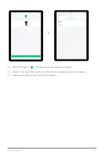
Page 69: ...o the Main Page of the APP Tap on the and select Add a Device 13 Press and hold F3 on the RTK Module Console for at least 3 seconds and release after hearing a beep All the Status Indicator will flashes indicating that the RTK Module is ready to be added 14 Add the Device by Entering the Device S N Manually or Scanning the QR Code on the Device 15 Rename the RTK Module and Tap on CONFIRM to Save ...

Page 70: ...RALIA 70 16 If the APP display the Device has been added successfully 17 Return to the Device Menu and check if the Device is displayed in your list of Device 18 Please restart APP once the binding is completed ...

Page 71: ...nnected before Opening APP 01 Turn ON the Remote Controller Open XAG One APP 02 Tap on My to access Account Menu 03 Tap on Device PREREQUISITE IMPORTANT LNT Local Network Terminal must be connected to an external internet available network indicated by the WAN indicator on the LNT Device Binding can only be achieved once all the Indicators on LNT is ON ...

Page 72: ...hen Tap on for Device Binding 05 Tap on Remote Controller to start Binding 06 Tap on Settings to bring up the Available Wi Fi List 07 Select the corresponding ACS2 Wi Fi Default ACS2G Wi Fi Network ACS2_XXXXXXXXXXXX Default ACS2G Password 20070401 ...

Page 73: ...ep Wi Fi connection 09 Return to the APP and Tap on I m Connected to access Equipment Network Settings 10 Enter the LNT Wi Fi Network Name Password for the LNT Local Network Terminal then save the settings via Confirm Default LNT Wi Fi Network XAG XXXX Default LNT Password 20070401 Check ensure the entered LNT Network Name Password is Correct otherwise user will not be able to add the device Warni...

Page 74: ... Main Page of the APP Tap on the and select Add a Device 12 Press and hold the Power Button of the Remote Controller for 6 10 seconds and release after all indicators are flashing Red This indicates that the Remote Controller is now ready to be added 13 Add the Device by Scanning the QR Code on the Device or Enter the Device S N Manually 14 Rename the Remote Controller and Tap Complete to Save CHE...

Page 75: ...USTRALIA 15 If the APP display the Device has been added successfully 16 Return to the Device Menu and check if the Device is displayed in your list of Device 17 Please restart APP once the binding is completed ...

Page 76: ...fore logging into Open APP PREREQUISITE LNT Local Network Terminal must be connected to an external internet available network indicated by the WAN indicator on the LNT Device Binding can only be achieved once all the Indicators on LNT are ON IMPORTANT 01 Turn ON the Remote Controller Open XAG One APP 02 Tap on My to access Account Menu 03 Tap on Device ...

Page 77: ...or 2 seconds then release it Repeat the press hold once more for 2 seconds then release it again The Wireless Communication indicator 3rd Indicator will start flashing orange indicating the Aircraft is ready for binding 07 Tap on Settings to bring up the Available Wi Fi List 08 Select the corresponding Aircraft Wi Fi Default Aircraft Wi Fi Network XAG_XXXXXXXXXXXX Aircraft S N Default Aircraft Pas...

Page 78: ...d Tap on I m Connected to access Equipment Network Settings 10 Return to the APP and Tap on I m Connected to access Equipment Network Settings 11 Enter the LNT Wi Fi Network Name Password for the LNT Local Network Terminal then save the settings via Confirm Default LNT Wi Fi Network XAG XXXX Default LNT Password 20070401 Check ensure the entered LNT Network Name Password is Correct otherwise user ...

Page 79: ... LNT Wi Fi Check Ensure the LNT Wi Fi Network is connected 12 Return to the Main Page of the APP Tap on the and select Add a Device 13 Add the Device by Scanning the QR Code on the Device or Enter the Device S N Manually 14 Rename the Aircraft and Tap Confirm to Save 15 If the APP display the Device has been added successfully ...

Page 80: ...XAG AUSTRALIA 80 16 Return to the Device menu and check if the Device is displayed in your list of Devices 17 Please restart the APP once the binding is completed ...

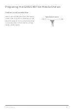
Page 81: ...Mobile Station Station Location selection Select solid and flat ground with open space above There should be no obstacles over the elevation angle of 15 for continuous tracking and observation of the satellite and high quality satellite signals ...

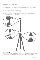
Page 82: ...e Plate on top of the Tripod as shown 04 Tighten the fixing bolts on the Tripod to firmly secure the Balance plate 05 Place the Rover assembled in Step 2 from top into the spacing hole and close the buckle to complete the assembly of the Mobile Station 2 1 5 4 3 IMPORTANT Adjust the three retractable legs of the Tripod accordingly to ensure the bubble on the Balance Plate is centred and level Unle...

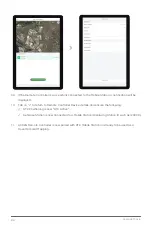
Page 83: ...ioning Status will refresh and display as FIX Normal 08 RTK Mobile Station is now ready for USE CHECK Check Ensure the Positioning Status of the RTK Module Console is in RTK Mode Solid Blue Check Ensure the Positioning Status on the APP is now displaying as FIX Normal IMPORTANT Please be patient the device may take up to 30 seconds before coming ONLINE XAG GNSS RTK Mobile Station provides Low Prec...

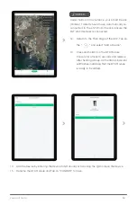
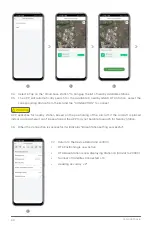
Page 84: ...work Terminal Wi Fi Network had been setup Connected Device binding of XRTK4 Mobile Station had been setup ACS2 RTK Module had been attached PREREQUISITE IMPORTANT Please be patient the devices may take up to several minutes before coming ONLINE 04 Tap on Mobile Station for Mobile Station Device Details and ensure the Positioning Status is now displaying as FIX Normal Preparing the ACS2G Remote Co...

Page 85: ...ce Menu Tap on Remote Controller for Device details 06 Tap on Set Base Station for Base Station Settings 07 The APP will automatically detect and display the available base station nearby 08 Select the available base station and tap Connect ...

Page 86: ...ayed 10 Tab on to return to Remote Controller Device details and ensure the following RTK Positioning is now RTK Active Set Base Station is now Connected to a Mobile Station Displaying Station ID such as XXXX 11 ACS2G Remote Controller is now paired with RTK Mobile Station and ready to be used as a Rover for Field Mapping ...

Page 87: ... Aircraft for Device Detail 03 Tap on the for Positioning System then taps on RTK Base Station 1 2 3 LNT Local Network Terminal Wi Fi Network had been set up Connected Device binding of GNSS XRTK4 Mobile Station had been set up Connected Device binding of Aircraft had been set up Connected Devices are ON and displaying as Online in Device Menu PREREQUISITE ...

Page 88: ...es for nearby station based on the positioning of the Aircraft If the Aircraft is placed indoor or area where it can t be positioned the APP may not be able to search for Nearby Station Warning 07 Return to the Device Detail and confirm RTK Positioning is now Active RTK Base Station is now displaying Station ID Similar to XXXX Number of Satellites Connected 16 Heading Accuracy 2º 4 5 6 7 06 When t...

Page 89: ...g Aircraft for Device Detail 03 On the Universal Information Tab Tap on Pair with ControlStick 1 2 3 LNT Local Network Terminal Wi Fi Network had been set up Connected Device binding of ACS2G Remote Controller had been set up Connected Device binding of Aircraft had been set up Connected Devices are ON and displaying as Online in Device Menu PREREQUISITE ...

Page 90: ...e corresponding Remote Controller and then tap on Pair for Pairing 05 When the Pairing is completed it will display Pairing Successful 06 Return to the Device Menu and check the status of Bind Remote Controller is now Paired 4 5 6 ...

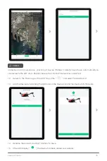
Page 91: ... Set as operation Device 1 2 3 Aircraft are required to be set as operation devices before they can be used for Aerial Survey Spraying or Spreading LNT Local Network Terminal Wi Fi Network had been set up Connected Device binding of GNSS XRTK4 Mobile Station had been set up Connected Device binding of Aircraft had been set up Connected Devices are ON and displaying as Online in Device Menu PREREQU...

Page 92: ...XAG AUSTRALIA 92 04 The corresponding aircraft is now set as an operation device and is available for operation Ⓝ Notes Maximum of 2 Aircraft can be set and used for operation simultaneously 4 ...

Page 93: ... that had imported the data Internet Access to Cloud for Data Retrieval Using the same XAG Account PREREQUISITE This section is primarily for previous XAG Pilots to access Fields that had been previously planned and Maps that XAG s related survey equipment had surveyed XAG One APP supports multiple methods in Field Planning Create a new field Import Data This Section will provide step by step inst...

Page 94: ...ll be displayed 05 Alternatively the user may choose to search for the fields as well 06 Select 1 or Several fields then confirm to start importing the field to this Smart Device 07 After the field is imported please refresh the List and find the imported field is now available ...

Page 95: ...ith the field or pilots who have surveyed the area for an HD Map Satellite map accuracy varies and is not recommended for a new or inexperienced pilot unfamiliar with the field or the Aircraft The pilot should be cautious with the possible deviation between the satellite map and the RTK Position based aircraft 01 Open XAG One APP 02 Tap on to expand the Options menu then Tap on Create a new field ...

Page 96: ... on one of these to expand the menu for alternate options 06 Tap on the desired location on the map to Add points 07 Alternatively the User can use the crosshair to add boundary obstacles and No spray zone Adding Point via APP Press on APP Removing Point via APP Press on APP 08 Review the Map and the points added then Tap Confirm 09 Enter Insert Field Information then Tap Complete to Save 03 Then ...

Page 97: ...97 XAG AUSTRALIA 10 The field has now been created 11 Tap on to review the List of Field HD Map Device The field is now available for Route Planning ...

Page 98: ...p Connected Device binding of XRTK4 Mobile Station had been setup ACS2 RTK Module had been attached PREREQUISITE 01 Tap on to expand the Options menu then tap on Create a new field 02 Tap on to position the map to your current location 03 Tap on to select the Remote Controller for Manual Mapping ...

Page 99: ...PP Press on APP Adding Point via Remote Controller Press Button A on Remote Controller Removing Point via Remote Controller Press Button B on Remote Controller Field Boundary Field Boundary are individual points that form an application zone Obstacle Obstacles are individual points that form an area where the RPA will not fly enter as it has been designated as a potential hazard to the RPA Non Spr...

Page 100: ...AUSTRALIA 100 07 Enter Insert Field Information then Tap Complete to Save 08 The field has now been created 09 Tap on to review the List of Field HD Map Device the field is now available for Route Planning ...

Page 101: ...sponding fields for additional options 03 Additional options include Aerial Flight Aerial Survey Manage fields Share Field and more 04 Proceed to Manage Fields to edit or pre plan the fields 05 At the bottom of the screen there are two available options Field Modify field information Route Route Pre Planning with Basic Flight Parameters ...

Page 102: ...e Points Tap on the points then select Delete Point Non Spraying Zone Add Points Tap once between the segments and drag the to add Points Move Points Drag the points to the appropriate location Delete Points Tap on the points then select Delete Point Select Edit Field and then Tap on one of the Boundary Icons to switch options between Field Boundary Obstacles or No Spraying Zone Points are highlig...

Page 103: ...stom Route Custom Route based on the points that the user had added Parameters Route Direction The Direction of each Flight Route Route Spacing The Spacing Distance between each Flight Route Boundary Safety Distance The Safety Distance from the Boundary Obstacle Safety Distance The Safety Distance from the Obstacles ...

Page 104: ...APP is up to date 06 Check and ensure there are sufficient battery for the operation Including LNT Remote Controller and RTK Station Battery 07 Check and ensure the Remote Controller is paired to all aircraft and ready to operate the aircraft and manually avoid obstacles promptly or during an emergency 08 Check and ensure the Communication is Normal RPA enters RTK Mode RPA Heading Accuracy 2º Numb...

Page 105: ...A Aerial Survey Real Terra IMPORTANT Maximum acreage for RealTerra aerial survey is 6 66 ha Functions of Real Terra with Local Network Terminal is NOT yet available and will be release for use around June 2022 Warning ...

Page 106: ...T RTK Remote Controller and Aircraft Completed Setting Aircraft as Operation Device Completed Pre Flight Checklist Completed Field Planning PREREQUISITE 01 Open XAG One APP and tap on the Operation 02 The interface displays the status and the available aircraft for the Task ...

Page 107: ...ll assigned the aircraft for the operation of this field Spray Settings Route Settings is now available for setting Review adjust the settings Refer to Page 107 108 for Spray Settings Route Settings then tap on Start Operation 05 Complete the Start Operation checklist then swipe start to begin 06 The APP is now uploading route to the Aircraft completing Self check upon completion the aircraft will...

Page 108: ...nt to Task Area Adopt Safe Point Planning Enabled This function will allow Pilots to add Guide Point to guide the flight route of the RPA from Take off point to the Task Area Disabled Disabling this function will enable the options for Set Guide Point for Return Set Guide Point for Return Enabled This function will allow Pilots to add Guide Point to guide the flight route of the RPA from Entering ...

Page 109: ...errain Terrain Following Settings Obstacle Avoidance Dynamic Radar Settings for Obstacles Avoidance Automatic route optimization Break point is the location where the autonomous task was interrupted by either Manual take over via APP or Remote Controller empty liquid tank or Low Voltage battery Enable The RPA will automatically optimize and travel to the Break point and resume its flight from the ...

Page 110: ...ency Control via ACS2G Remote Controller Motion Control Hover Switch Mode Hover Press the Hover Button to command the UAV to Hover Switch Mode Press and Hold the Hover Button to switch Mode The Remote Controller will exit Manual Control and enter Autonomous Mode the Controller will also broadcast Autonomous Mode Move the UAV Forward Move the UAV Backward Move the UAV Sideway to the Left Move the U...

Page 111: ...o thoroughly clean UAV after each operation 01 Refill the Liquid Tank with soap water or soap powder water and engage all nozzle to drain and clean out remaining residues within the spray system 02 Refill the Liquid Tank with clean water and engage all nozzle to drain and clean out remaining soap water within the spray system 03 Place an empty Liquid Tank and engage all nozzle to drain and clean o...

Page 112: ... switch between the aircraft After switching the Aircraft the APP will display the selected Aircraft Name at the Aircraft status Bar Switch Control IMPORTANT Inspect and ensure the Take off and Landing Location must be chosen separately for each RPA so there will be no conflict for the aircraft during the flight Inspect and ensure the Outbound and RTH height should have a minimum of 1m separation ...

Page 113: ...Frequency 2 4000GHz 2 4835GHz Maximum Thrust Weight Ratio 1 8 Hovering Precision good GNSS signal RTK Enabled 10cm horizontal 10cm vertical RTK Disabled 0 6m horizontal 0 3m vertical radar enabled 0 1m Continuous High Precision Navigation Time without Signal 600s Hovering Duration 13 5min with No load 20000mAh Takeoff Weight 29 8kg 6 8min with Full load 20000mAh Takeoff Weight 45 8kg Maximum Flyin...

Page 114: ...in Maximum flow rate single pump 5L min Peristaltic Pump Image Sensor 1 2 3inch 12M CMOS Sensor Lens FOV 112 2 7mm 16 8mm 35mm Equivalent Mechanical Shutte 1 200 1 2000s Image Format JPG Power 10W Optimum Operating Temperature 10 40 C XAG RealTerra Dimensions 50 x 36 7 x 29mm Video Resolution 720P 1080P Video Coding Format H 264 Frame Rate 30fps Focal Length 2 75mm Image Sensor 1 2 95inch 2M CMOS ...

Page 115: ...rating Frequency 24GHz Sensing Mode Millimeter wave Imaging MIMO Sensing Parameters Obstacle s Position Distance Direction of Motion Relative Velocity Field of View FOV Horizontal 40 Vertical 45 Relative Height of Safe Obstacle Avoidance 1 5m Relative Speed of Safe Obstacle Avoidance 2 5m Distance between the propeller tip and obstacle after the UAV brakes and hovers stably Relative Speed of Safe ...

Page 116: ...Motor Model VC13180 Maximum Continuous Operating Current 80A Maximum Operating Voltage 56 6V Electronic Speed Controller Model P4718 Diameter Screw Pitch 47 x 18inch Foldable Propeller Rated Voltage DC50V Operating Voltage DC25V 55V Rated Torque 150Kg cm 50V Rated Current 0 5A 50V No Load Speed 400 second Tilt Servo Propulsion System ...

Page 117: ...4 Communication Protocol Wi Fi Operating Frequency 2400 2483 5 MHz Antenna TNC Port 2dBi Warranty Period 12 Months Dimensions 101mm x 86mm x 37mm Weight Approx 335g Power Input DC 40 54V B13960S Battery Adaptor Power Output DC 12V 3A Power 36W Operating Temperature 0 50 C IP Rating IP54 Power Adapter Local Network Terminal Local Network Terminal ...

Page 118: ...erature 20 to 55 Storage Temperature 20 C to 20 C 1 Month 20 C to 45 C 1 3 Months 20 C to 55 C 3 12 Months Max Transmission Distance Unobstructed free of interference 800 Meters Charging Voltage Current 05V 2A 09V 1 5A 12V 1 5A Mesh Network Supported Voice Broadcast Supported RTK Operating Frequency GPS L1 L2 GLONASS L1 L2 BDS B1 B2 Galileo E1 E5b Positioning Accuracy With strong RTK Signal Vertic...

Page 119: ... Energy 962 Wh Rated Output 48 1V 120A Operating Temperature 10 C to 45 C Charging Temperature 10 C to 40 C Storage Temperature 10 C to 30 C IP Rating IP65 Compatible Aircraft XAG V40 2021 XAG P40 2021 XAG P80 2021 Compatible Chargers CM12500P GC4000 Charging Voltage 56 55V Battery Charging Time Warranty Details 6 Months Smart Battery ...

Page 120: ...re 20 50 C Storage Temperature 40 85 C Relative Humidity 100 condensation Warranty Details 12 Months GNSS Performance Specifications Compatible motherboard K726 GNSS Frequency BDS GPS GLONASS Galileo QZSS B1I B2I B3I B1C B2a L1 L2 L5 L1 L2 L2C E1 E5a E5b L1 L2 L5 RTK Positioning Accuracy Horizontal 10mm 1ppm RMS Vertical 15mm 1ppm RMS Initialization time Typical 10 seconds Initialization Reliabili...

Page 121: ...z 5 735 5 835GHz Channel spacing 20 MHz Frequency error frequency stability 10 ppm Communication mode Full duplex Communication protocol Transparent Forward error correction FEC Data rate 6Mbps Modulation OFDM Emission performance RF output power Less than 1W Subject to regional SRRC FCC CE standards Reception performance Decoding sensitivity 90dbm Battery terminal 1 SIM card slot 3 Model B4100 Di...

Page 122: ...lustrations photos methods processes etc belongs to XAG Australia and is protected by copyright law No individual or organization may imitate extract translate distribute or reproduce or quote all the contents of this manual without any written authorization Copyright 2022 XAG Australia All Rights Reserved ...

Reviews: