background image


Mounting for NODE starts on page 12

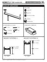
DO NOT DISCARD!

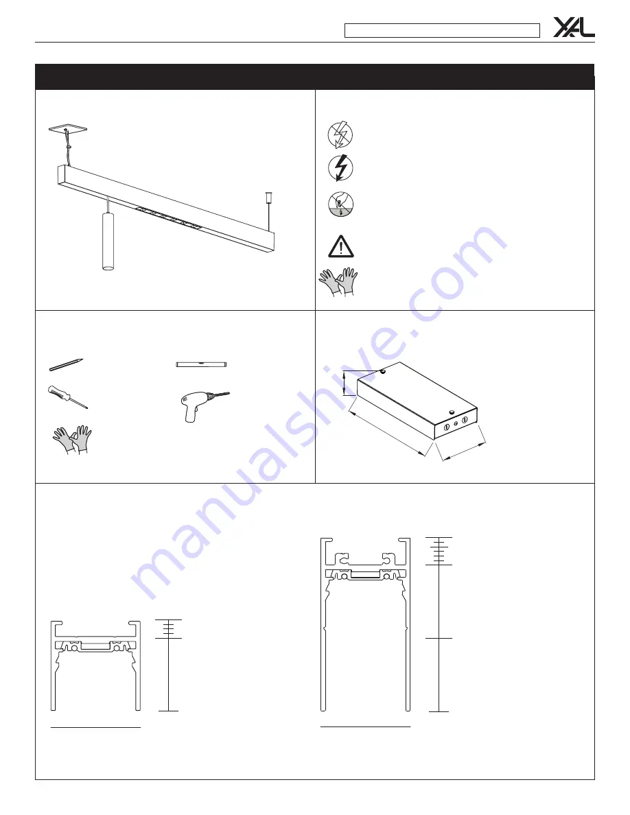
level

TOOLS REQUIRED (not included)

screwdriver

ESD gloves

pencil

drill

SIGN LEGEND

power OFF

power ON

don’t touch the LEDs

attention

use ESD gloves

1 ¼" 

31.8mm

2 ⅜" 

/

 60.5mm

2" 

50.8mm

1" 

25.4mm

MOVE IT SYSTEM 1.1

MOVE IT SYSTEM 1.2

1 ¼" 

31.8mm

1" 

25.4mm

1 ¼" 

31.8mm

POWER SUPPLY DIMENSIONS

2  ⅝"

7 ⅛

"

15"

MOVE IT 1 .1  

/

 1.2  

suspended

MOUNTING INSTRUCTIONS

XAL Inc.   150 Hawley Rd.   Oxford, CT 06478   T: +1 203.262.9990   www.xalusa.com

MI-V02

4/13/21

7 / 14

Summary of Contents for MOVE IT 1.1

Page 1: ...power OFF power ON don t touch the LEDs attention use ESD gloves 1 31 8mm 2 60 5mm 2 50 8mm 1 25 4mm MOVE IT SYSTEM 1 1 MOVE IT SYSTEM 1 2 1 31 8mm 1 25 4mm 1 31 8mm POWER SUPPLY DIMENSIONS 2 7 15 MOVE IT 1 1 1 2 suspended MOUNTING INSTRUCTIONS XAL Inc 150 Hawley Rd Oxford CT 06478 T 1 203 262 9990 www xalusa com MI V02 4 13 21 7 14 ...

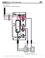
Page 2: ...WIRING DIAGRAMS LINE DIM CONTROL 0 10V NON DIM ZIGBEE DIM MOVE IT 1 1 1 2 suspended MOUNTING INSTRUCTIONS XAL Inc 150 Hawley Rd Oxford CT 06478 T 1 203 262 9990 www xalusa com MI V02 4 13 21 8 14 ...

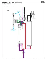
Page 3: ...IMMING Channel 1 Channel 2 Two 0 10V Dimmers By others Three Way Primary wiring configuration Feeder Cable to track MOVE IT 1 1 1 2 suspended MOUNTING INSTRUCTIONS XAL Inc 150 Hawley Rd Oxford CT 06478 T 1 203 262 9990 www xalusa com MI V02 4 13 21 9 14 ...

Page 4: ...M DALI connect grounding attach to cover not shown DA DA Ground IN DA DA OUT MOVE IT 1 1 1 2 suspended MOUNTING INSTRUCTIONS XAL Inc 150 Hawley Rd Oxford CT 06478 T 1 203 262 9990 www xalusa com MI V02 4 13 21 10 14 ...

Page 5: ...tion 6 Adjust aircraft cables to poper height Turn OFF power source before installation 7 Thread aircraft cable through bracket 7 2 15 2 Install converter box ceiling utility room See page 4 chart for max distance RED BLACK 10 Thread feeder through bracket 12 Place bracket into junction box 13 Screw bracket into J box 14 Click cover onto mounting plate springs MOVE IT 1 1 1 2 suspended MOUNTING IN...

Page 6: ...rews to secure connector 19 Slide next track onto linear connector 15 Connect feeder to converter box 17 Insert linear connector 16 Snap feeder clip into track 21 B Track 1 2 Turn tentioning screw counter clockwise Repeat steps 17 21 for additional channels 20 Use screws to secure connector again 21 A Track 1 1 Turn tentioning screw clockwise RED BLACK 1 MOVE IT 1 1 1 2 suspended MOUNTING INSTRUCT...

Page 7: ...ks 29 Installation complete 25 24 Insert X Connector optional Use screws to attach X connection ø 2 2 ø 2 2 6 6 ø 2 2 ø 2 2 6 6 TYPE 1 NODE power feed TYPE 2 NODE daisy chain L 2 ø 2 channel L MOVE IT 1 1 1 2 suspended MOUNTING INSTRUCTIONS MOVE IT 1 2 NODE suspended XAL Inc 150 Hawley Rd Oxford CT 06478 T 1 203 262 9990 www xalusa com MI V02 4 13 21 13 14 ...

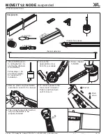
Page 8: ...then down until it clicks in Push in Push down 6 The connector must be inserted fully into the NODE to be properly installed 7 3 Screw channel to NODE click 4 Remove plastic cap from NODE and attach connector to channel 1 Attach NODE pieces to ceiling before con necting the channels to the NODEs Follow steps 1 16 on previous pages for suspension installation NODE channel from below channel from ab...

Page 9: ...29 Il faut que le circuit de LED soit fermé avant de connecter le convertisseur XAL ne assume pas la garantie si cette norme ne se respecte pas ES La instalación la puesta en marcha y el mantenimiento sólo deben realizarse por personal especializado considerando esta guía de instalación y todas las normas y reglamentaciones vigentes Asegurarse de la aptitud eléctrica mecá en esta p ej Limpieza Esp...

Reviews: